Ac Inductor Circuits
AC inductor circuits: Inductors do not behave the same as resistors. Whereas resistors simply oppose the flow of electrons through them (by dropping a voltage directly proportional to the current), inductors oppose changes in current through them, by dropping a voltage directly proportional to the rate of change of current. In accordance with Lenz's Law, this induced voltage is always of such a polarity as to try to maintain current at its present value. That is, if current is increasing in magnitude, the induced voltage will “push against” the electron flow; if current is decreasing, the polarity will reverse and “push with” the electron flow to oppose the decrease. This opposition to current change is called reactance, rather than resistance.
Expressed mathematically, the relationship between the voltage dropped across the inductor and rate of current change through the inductor is as such:

The expression di/dt is one from calculus, meaning the rate of change of instantaneous current (i) over time, in amps per second. The inductance (L) is in Henrys, and the instantaneous voltage (e), of course, is in volts. Sometimes you will find the rate of instantaneous voltage expressed as “v” instead of “e” (v = L di/dt), but it means the exact same thing. To show what happens with alternating current, let's analyze a simple inductor circuit: (Figure below)
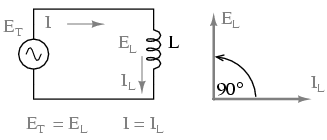
Pure inductive circuit: Inductor current lags inductor voltage by 90o.
If we were to plot the current and voltage for this very simple circuit, it would look something like this: (Figure below)
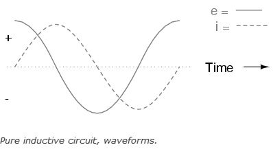
Remember, the voltage dropped across an inductor is a reaction against the change in current through it. Therefore, the instantaneous voltage is zero whenever the instantaneous current is at a peak (zero change, or level slope, on the current sine wave), and the instantaneous voltage is at a peak wherever the instantaneous current is at maximum change (the points of steepest slope on the current wave, where it crosses the zero line). This results in a voltage wave that is 90o out of phase with the current wave. Looking at the graph, the voltage wave seems to have a “head start” on the current wave; the voltage “leads” the current, and the current “lags” behind the voltage. (Figure below)
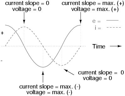
Current lags voltage by 90o in a pure inductive circuit.
REVIEW:
- Inductive reactance is the opposition that an inductor offers to alternating current due to its phase-shifted storage and release of energy in its magnetic field. Reactance is symbolized by the capital letter “X” and is measured in ohms just like resistance (R).
- Inductive reactance can be calculated using this formula: XL = 2πfL
- The angular velocity of an AC circuit is another way of expressing its frequency, in units of electrical radians per second instead of cycles per second. It is symbolized by the lower-case Greek letter “omega,” or ω.
- Inductive reactance increases with increasing frequency. In other words, the higher the frequency, the more it opposes the AC flow of electrons.