Analysis Of Series Magnetic Circuit
Analysis of Series magnetic circuit: Consider first a simple magnetic circuit, shown in Figure (A) with a single core material having uniform cross sectional area A and mean length of flux path l. Reluctance offered to the flow of flux is ℜ. The corresponding electrical representation is rather simple. Due to the fact that NI=φℜ=HI, the equivalent electrical circuit is also drawn beside the magnetic circuit. Polarity of mmf is decided on the basis of the direction of the flux which is clockwise inside the core in this case. Although in the actual magnetic circuit there is no physical connection of the winding and the core, in the electrical circuit representation mmf and reluctance are shown to be connected. One should not feel disturbed by this as because the relationship between mmf and flux prompted us to draw an electrical equivalent to facilitate easier calculation and neat visualization of the actual problem.
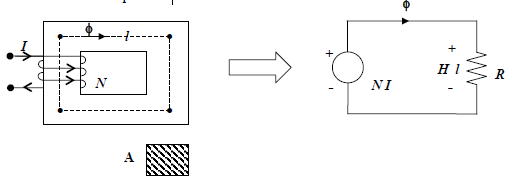 fig (A)
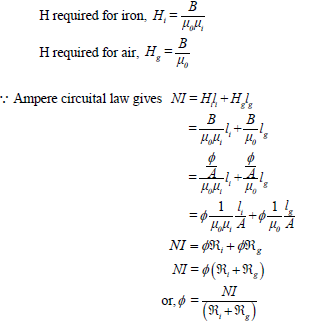
Let us now consider another magnetic circuit which is similar to the earlier one but has a small air gap of length lg as shown in Figure (B) and note that it is a series circuit involving two mediums, namely (i) iron and (ii) air. It is a series circuit because same flux (φ) has to flow through the mediums. Hence total reluctance will be the sum of reluctances of iron and air()airiℜ=ℜ ℜ.
For this circuit basic equations can be developed as follows:
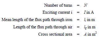
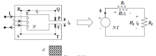 fig .. (B)
If the cross sectional area A is constant throughout, flux density B=φ/A will be also constant both in iron and air path. Since value of permeabilities are different for iron and air, the corresponding alues of H too will be different.