Auto-transformer
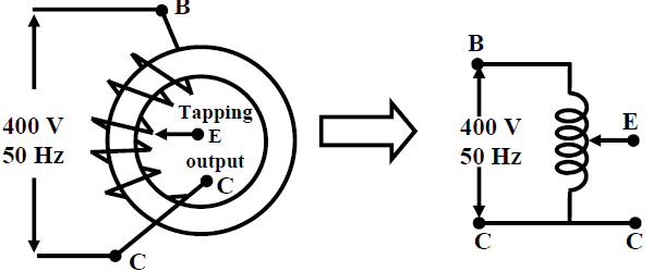
Auto-Transformer: So far we have considered a 2-winding transformer as a means for changing the level of a given voltage to a desired voltage level. It may be recalled that a 2-winding transformer has two separate magnetically coupled coils with no electrical connection between them. In this lesson we shall show that change of level of voltage can also be done quite effectively by using a single coil only. The idea is rather simple to understand. Suppose you have a single coil of 200 turns (= NBC) wound over a iron core as shown in figure 27.1. If we apply an a.c voltage of 400 V, 50 Hz to the coil (between points B and C), voltage per turn will be 400/200 = 2 V. If we take out a wire from one end of the coil say C and take out another wire tapped from any arbitrary point E, we would expect some voltage available between points E and C. The magnitude of the voltage will obviously be 2 × NEC where NEC is the number of turns between points E and C. If tapping has been taken in such a way that NEC = 100, voltage between E and C would be 200 V. Thus we have been able to change 400 V input voltage to a 200 V output voltage by using a single coil only. Such transformers having a single coil with suitable tapings are called autotransformers.
It is possible to connect a conventional 2-winding transformer as an autotransformer or one can develop an autotransformer as a single unit.\
 fig(A) transformer with a single coil
2-winding transformer as Autotransformer: Suppose we have a single phase 200V/100V, 50Hz, 10kVA two winding transformer with polarity markings. Then the coils can be connected in various ways to have voltage ratios other than 2 also, as shown in figure (B)
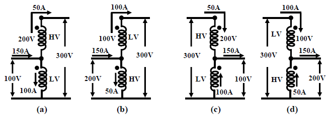
fig(B) A two winding transformer connected as an autotransformer in various ways.
Let us explain the one of the connections in figure B(a) in detail. Here the LV and the HV sides are connected in additive series. For rated applied voltage (100V) across the LV winding, 200V must be induced across the HV winding. So across the whole combination we shall get a voltage of 300V. Thus the input voltage is stepped up by a factor of 3 (300 V/100 V). Now how much current can be supplied to a load at 300 V? From the given rating of the transformer we know, IHV rated = 50 A and ILV rated = 100 A. Therefore for safe operation of the transformer, these rated currents should not be exceeded in HV and LV coils. Since the load is in series with the HV coil, 50A current can be safely supplied. But a current of 50A in the HV demands that the LV winding current must be 100A and in a direction as shown, in order to keep the flux in the core constant. Therefore by applying KCL at the junction, the current drawn from the supply will be 150A. Obviously the kVA handled by the transformer is 30 kVA and without overloading either of the windings. It may look a bit surprising because as a two winding transformer its rating is only 10 kVA. The explanation is not far to seek. Unlike a two winding transformer, the coils here are connected electrically. So the kVA transferred from supply to the load side takes place both inductively as well as conductively – 10kVA being transferred inductively and remaining 20kVA transferred conductively. The other connections shown in (b), (c) and (d) of figure (B) can similarly explained and left to the reader to verify.