Capacitor Split-phase Motor
Capacitor Split-phase Motor:
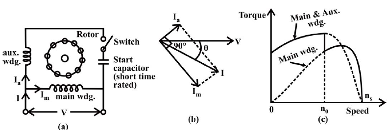
The motor described earlier, is a simple one, requiring only second (auxiliary) winding placed at a space angle of 90° from the main winding, which is there in nearly all such motors as discussed here. It does not need any other thing, except for centrifugal switch, as the auxiliary winding is used as a starting winding. But the main problem is low starting torque in the motor, as this torque is a function of, or related to the phase difference (angle) between the currents in the two windings. To get high starting torque, the phase difference required is 90° (Fig.(A)b), when the starting torque will be proportional to the product of the magnitudes of two currents. As the current in the main winding is lagging by φm, the current in the auxiliary winding has to lead the input voltage by φa, with (φm φa=90°). φa is taken as negative (-ve), while mφ is positive ( ve). This can be can be achieved by having a capacitor in series with the auxiliary winding, which results in additional cost, with the increase in starting torque, The two types of such motors are described here.
Capacitor-start Motor:
fig(A)
The schematic (circuit) diagram of this motor is given in Fig. (A)a. It may be observed that a capacitor along with a centrifugal switch is connected in series with the auxiliary winding, which is being used here as a starting winding. The capacitor may be rated only for intermittent duty, the cost of which decreases, as it is used only at the time of starting. The function of the centrifugal switch has been described earlier. The phasor diagram of two currents as described earlier, and the torque-speed characteristics of the motor with/without auxiliary winding, are shown in Fig. (A)b and Fig. (A)c respectively. This motor is used in applications, such as compressor, conveyor, machine tool drive, refrigeration and air-conditioning equipment, etc.