Characteristics Of A Separately Excited Generator
Characteristics of a separately excited generator:
No load or Open circuit characteristic: In this type of generator field winding is excited from a separate source, hence field current is independent of armature terminal voltage as shown on figure (A). The generator is driven by a prime mover at rated speed, say n rps. With switch S in opened condition, field is excited via a potential divider connection from a separate d.c source and field current is gradually increased. The field current will establish the flux per pole φ. The voltmeter V connected across the armature terminals of the machine will record the generated emf (EG = (pz/a)φn=kφn). Remember pza is a constant (k) of the machine. As field current is increased, EG will increase. EG versus If plot at constant speed n is shown in figure (B).
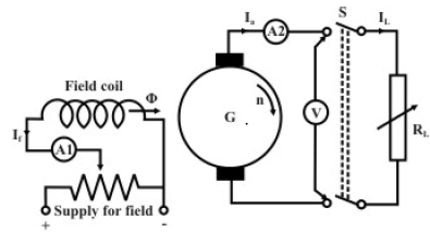 fig(A)connection of separately excited generator
It may be noted that even when there is no field current, a small voltage (OD) is generated due to residual flux. If field current is increased, φ increases linearly initially and O.C.C follows a straight line. However, when saturation sets in, φ practically becomes constant and hence Eg too becomes constant. In other words, O.C.C follows the B-H characteristic, hence this characteristic is sometimes also called the magnetisation characteristic of the machine.
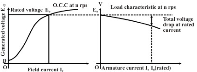
fig(B) NO load & load characterstics of a separately excited generator
It is important to note that if O.C.C is known at a certain speed nl, O.C.C at another speed n2 can easily be predicted. It is because for a constant field current, ratio of the generated voltages becomes the ratio of the speeds as shown below.
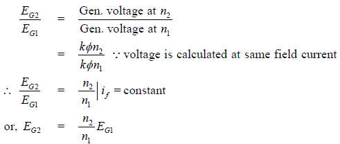
Therefore points on O.C.C at n2 can be obtained by multiplying ordinates of O.C.C at n1 with the ratio 21nn. O.C.C at two different speeds are shown in the following figure (C).
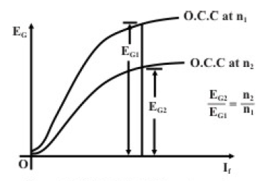
fig(C)O.C.C at different speed
Load characteristic of separately excited generator: Load characteristic essentially describes how the terminal voltage of the armature of a generator changes for varying armature current Ia. First at rated speed, rated voltage is generated across the armature terminals with no load resistance connected across it (i.e., with S opened) by adjusting the field current. So for Ia = 0, V = Eo should be the first point on the load characteristic. Now with S is closed and by decreasing RL from infinitely large value, we can increase Ia gradually and note the voltmeter reading. Voltmeter reads the terminal voltage and is expected to decrease due to various drops such as armature resistance drop and brush voltage drop. In an uncompensated generator, armature reaction effect causes additional voltage drop. While noting down the readings of the ammeter A2 and the voltmeter V, one must see that the speed remains constant at rated value. Hence the load characteristic will be drooping in nature as shown in figure (B).