Construction Of Three-phase Induction Motor
Construction of Three-phase Induction Motor: This is a rotating machine, unlike the transformer, described in the previous module, which is a static machine. Both the machines operate on ac supply. This machine mainly works as a motor, but it can also be run as a generator, which is not much used. Like all rotating machines, it consists of two parts − stator and rotor. In the stator (Fig. A), the winding used is a balanced three-phase one, which means that the number of turns in each phase, connected in star/delta, is equal. The windings of the three phases are placed 130o(electrical) apart, the mechanical angle between the adjacent phases being [2*120o/P], where p is no. of poles. For a 4-pole (p = 4) stator, the mechanical angle between the winding of the adjacent phases, is [2×120°/4=120°/2=60°]. The conductors, mostly multi-turn, are placed in the slots, which may be closed, or semi-closed, to keep the leakage inductance low. The start and return parts of the winding are placed nearly , 180° or (180°−β)apart. The angle of short chording (β) is nearly equal to 30o , or close to that value. The short chording results in reducing the amount of copper used for the winding, as the length of the conductor needed for overhang part is reduced. There are also other advantages. The section of the stampings used for both stator and rotor, is shown in Fig. (B). The core is needed below the teeth to reduce the reluctance of the magnetic path, which carries the flux in the motor (machine). The stator is kept normally inside a support
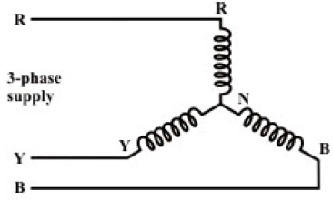 fig(A) schematic diagram of the stator windings in a three_phase induction motor
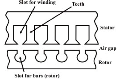 fig (B) section of a stamping of stator and rotor in im
There are two types of rotor used in IM, viz. squirrel cage and wound (slip-ring) one. The cage rotor (Fig. C) is mainly used, as it is cheap, rugged and needs little or no maintainance. It consists of copper bars placed in the slots of the rotor, short circuited at the two ends by end rings, brazed with the bars. This type of rotor is equivalent to a wound (slip-ring) one, with the advantage that this may be used for the stator with different no. of poles. The currents in the bars of a cage rotor, inserted inside the stator, follow the pattern of currents in the stator winding, when the motor (IM) develops torque, such that no. of poles in the rotor is same as that in the stator. If the stator winding of IM is changed, with no. of poles for the new one being different from the earlier one, the cage rotor used need not be changed, thus, can be same, as the current pattern in the rotor bars changes. But the no. of poles in the rotor due to the above currents in the bars is same as no. of poles in the new stator winding. The only problem here is that the equivalent resistance of the rotor is constant. So, at the design stage, the value is so chosen, so as to obtain a certain value of the starting torque, and also the slip at full load torque is kept within limits as needed.
The other type of rotor, i.e., a wound rotor (slip ring) used has a balanced three-phase winding (Fig. (D)), being same as the stator winding, but no. of turns used depends on the voltage in the rotor. The three ends of the winding are brought at the three slip-rings, at which points external resistance can be inserted to increase the starting torque requirement. Other three ends are shorted inside. The motor with additional starting resistance is costlier, as this type of rotor is itself costlier than the cage rotor of same power rating, and additional cost of the starting resistance is incurred to increase the starting torque as required. But the slip at full load torque is lower than that of a cage rotor with identical rating, when no additional resistance is used, with direct short-circuiting at the three slip-ring terminals. In both types of rotor, below the teeth, in which bars of a cage rotor, or the conductors of the rotor winding, are placed, lies the iron core, which carries the flux as is the case of the core in the stator. The shaft of the rotor passes below the rotor core. For large diameter of the rotor, a spider is used between the rotor core and the shaft. For a wound (slip-ring) rotor, the rotor winding must be designed for same no. of poles as used for the stator winding. If the no. of poles in the rotor winding is different from no. of poles in the stator winding, no torque will be developed in the motor. It may be noted that this was not the case with cage rotor, as explained earlier.
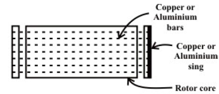
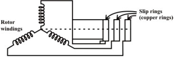
fig(c).. squirrel cage rotor of induction motor fig(D)....wound rotor (slip ring) of induction motor
The wound rotor (slip ring) shown in Fig.(D) is shown as star-connected, whereas the rotor windings can also be connected in delta, which can be converted into its equivalent star configuration. This shows that the rotor need not always be connected in star as shown. The No. of rotor turns changes, as the delta-connected rotor is converted into star-connected equivalent.