General Theory Permanent Magnet Moving Coil (Pmmc) Instruments
General Theory Permanent Magnet Moving Coil (PMMC) Instruments: The general theory of moving-coil instruments may be dealt with considering a rectangular coil of N turns, free to rotate about a vertical axis.
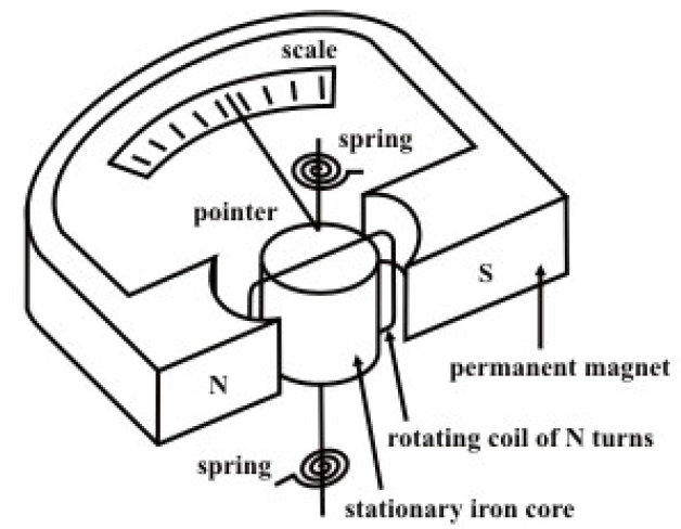 fig.A
fig.A 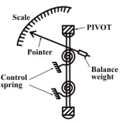 fig..B
Fig. (given above) shows the basic construction of a PMMC instrument. A moving coil instrument consists basically of a permanent magnet to provide a magnetic field and a small lightweight coil is wound on a rectangular soft iron core that is free to rotate around
its vertical axis. When a current is passed through the coil windings, a torque is developed on the coil by the interaction of the magnetic field and the field set up by the current in the coil. The aluminum pointer attached to rotating coil and the pointer moves around the calibrated scale indicates the deflection of the coil. To reduce parallax error a mirror is usually placed along with the scale. A balance weight is also attached to the pointer to counteract its weight (see Fig. B). To use PMMC device as a meter, two problems must be solved. First, a way must be found to return the coil to its original position when there is no current through the coil. Second, a method is needed to indicate the amount of coil movement. The first problem is solved by the use of hairsprings attached to each end of the coil as shown in Fig. A. These hairsprings are not only supplying a restoring torque but also provide an electric connection to the rotating coil. With the use of hairsprings, the coil will return to its initial position when no current is flowing though the coil. The springs will also resist the movement of coil when there is current through coil. When the developing force between the magnetic fields (from permanent magnet and electro magnet) is exactly equal to the force of the springs, the coil rotation will stop. The coil set up is supported on jeweled bearings in order to achieve free movement. Two other features are considered to increase the accuracy and efficiency of this meter movement. First, an iron core is placed inside the coil to concentrate the magnetic fields. Second, the curved pole faces ensure the turning force on the coil increases as the current increases.
It is assumed that the coil sides are situated in a uniform radial magnetic field of flux density B wb/m2, let the length of a coil side (within the magnetic field) be l(meter), and the distance from each coil side to the axis be r (meter).