Generation Of Sinusoidal (Ac) Voltage Waveform
Generation of Sinusoidal (AC) Voltage Waveform: if a single wire conductor is moved or rotated within a stationary magnetic field, an "EMF", (Electro-Motive Force) will be induced within the conductor due to this movement. From this tutorial we learnt that a relationship exists between Electricity and Magnetism giving us, as Michael Faraday discovered the effect of "Electromagnetic Induction" and it is this basic principal that is used to generate a Sinusoidal Waveform.

In the Electromagnetic Induction, tutorial we said that when a single wire conductor moves through a permanent magnetic field thereby cutting its lines of flux, an EMF is induced in it. However, if the conductor moves in parallel with the magnetic field in the case of points A and B, no lines of flux are cut and no EMF is induced into the conductor, but if the conductor moves at right angles to the magnetic field as in the case of points C and D, the maximum amount of magnetic flux is cut producing the maximum amount of induced EMF.
Also, as the conductor cuts the magnetic field at different angles between points A and C, 0 and 90o the amount of induced EMF will lie somewhere between this zero and maximum value. Then the amount of emf induced within a conductor depends on the angle between the conductor and the magnetic flux as well as the strength of the magnetic field.
An AC generator uses the principal of Faraday's electromagnetic induction to convert a mechanical energy such as rotation, into electrical energy, a Sinusoidal Waveform. A simple generator consists of a pair of permanent magnets producing a fixed magnetic field between a north and a south pole. Inside this magnetic field is a single rectangular loop of wire that can be rotated around a fixed axis allowing it to cut the magnetic flux at various angles as shown below.
Basic Single Coil AC Generator:
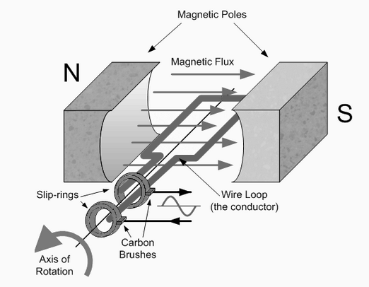
As the coil rotates anticlockwise around the central axis which is perpendicular to the magnetic field, the wire loop cuts the lines of magnetic force set up between the north and south poles at different angles as the loop rotates. The amount of induced EMF in the loop at any instant of time is proportional to the angle of rotation of the wire loop. As this wire loop rotates, electrons in the wire flow in one direction around the loop. Now when the wire loop has rotated past the 180o point and moves across the magnetic lines of force in the opposite direction, the electrons in the wire loop change and flow in the opposite direction. Then the direction of the electron movement determines the polarity of the induced voltage.
So we can see that when the loop or coil physically rotates one complete revolution, or 360o, one full sinusoidal waveform is produced with one cycle of the waveform being produced for each revolution of the coil. As the coil rotates within the magnetic field, the electrical connections are made to the coil by means of carbon brushes and slip-rings which are used to transfer the electrical current induced in the coil.
The amount of EMF induced into a coil cutting the magnetic lines of force is determined by the following three factors.
- Speed – the speed at which the coil rotates inside the magnetic field.
- Strength – the strength of the magnetic field.
- Length – the length of the coil or conductor passing through the magnetic field.
We know that the frequency of a supply is the number of times a cycle appears in one second and that frequency is measured in Hertz. As one cycle of induced emf is produced each full revolution of the coil through a magnetic field comprising of a north and south pole as shown above, if the coil rotates at a constant speed a constant number of cycles will be produced per second giving a constant frequency. So by increasing the speed of rotation of the coil the frequency will also be increased. Therefore, frequency is proportional to the speed of rotation, ( ƒ ∝ Ν ) where Ν = r.p.m.
Also, our simple single coil generator above only has two poles, one north and one south pole, giving just one pair of poles. If we add more magnetic poles to the generator above so that it now has four poles in total, two north and two south, then for each revolution of the coil two cycles will be produced for the same rotational speed. Therefore, frequency is proportional to the number of pairs of magnetic poles, ( ƒ ∝ P ) of the generator where P = is the number of "pairs of poles".
Then from these two facts we can say that the frequency output from an AC generator is:
![]()
A frequency is measured in Hertz
![]()
Where: Ν is the speed of rotation in r.p.m. P is the number of "pairs of poles" and 60 converts it into seconds.