Ideal Transformer
ideal transformer: Transformers are one of the most important components of any power system. It basically changes the level of voltages from one value to the other at constant frequency. Being a static machine the efficiency of a transformer could be as high as 99%.
Big generating stations are located at hundreds or more km away from the load center (where the power will be actually consumed). Long transmission lines carry the power to the load centre from the generating stations. Generator is a rotating machines and the level of voltage at which it generates power is limited to several kilo volts only a typical value is 11 kV. To transmit large amount of power (several thousands of mega watts) at this voltage level means large amount of current has to flow through the transmission lines. The cross sectional area of the conductor of the lines accordingly should be large. Hence cost involved in transmitting a given amount of power rises many folds. Not only that, the transmission lines has their own resistances. This huge amount of current will cause tremendous amount of power loss or I2r loss in the lines. This loss will simply heat the lines and becomes a wasteful energy. In other words, efficiency of transmission becomes poor and cost involved is high.
The above problems may addressed if we could transmit power at a very high voltage say, at 200 kV or 400 kV or even higher at 800 kV. But as pointed out earlier, a generator is incapable of generating voltage at these level due to its own practical limitation. The solution to this problem is to use an appropriate step-up transformer at the generating station to bring the transmission voltage level at the desired value as depicted in figure A where for simplicity single phase system is shown to understand the basic idea. Obviously when power reaches the load centre, one has to step down the voltage to suitable and safe values by using transformers. Thus transformers are an integral part in any modern power system. Transformers are located in places called substations. In cities or towns you must have noticed transformers are installed on poles – these are called pole mounted distribution transformers. These type of transformers change voltage level typically from 3-phase, 6 kV to 3-phase 440 V line to line.
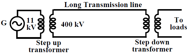
fig(A) A simple single phase power system.
Principle of operation: A transformer in its simplest form will consist of a rectangular laminated magnetic structure on which two coils of different number of turns are wound as shown in Figure B
The winding to which a.c voltage is impressed is called the primary of the transformer and the winding across which the load is connected is called the secondary of the transformer.
Ideal Transformer: To understand the working of a transformer it is always instructive, to begin with the concept of an ideal transformer with the following properties.
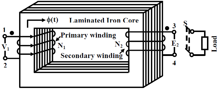
fig(B) a typical transformer
1. Primary and secondary windings has no resistance.
2. All the flux produced by the primary links the secondary winding i,e., there is no leakage flux.
3. Permeability μr of the core is infinitely large. In other words, to establish flux in the core vanishingly small (or zero) current is required.
4. Core loss comprising of eddy current and hysteresis losses are neglected.