Introduction Of D.c Machines
Introduction of D.C Machines: D.C machines were first developed and used extensively in spite of its complexities in the construction. The generated voltage in a coil when rotated relative to a magnetic field, is inherently alternating in nature. To convert this A.C voltage into a D.C voltage we therefore need a unit after the coil terminals. This unit comprises of a number commutator segments attached to the shaft of the rotor and a pair of suitably placed stationary carbon brushes touching the commutator segments. Commutator segments together with the fixed brushes do the necessary rectification from A.C to D.C and hence sometimes called mechanical rectifier.
Constructional Features: Figure (A) shows a sectional view of a 4-pole D.C machine. The length of the machine is perpendicular to the paper. Stator has got 4 numbers of projected poles with coils wound over it. These coils may be connected in series in order that consecutive poles produce opposite polarities (i.e., N-S-N-S) when excited from a source. Double layer lap or wave windings are generally used for armature. Essentially all the armature coils are connected in series forming a closed armature circuit. However as the coils are distributed, the resultant voltage acting in the closed path is zero thereby ensuring no circulating current in the armature. The junctions of two consecutive coils are terminated on to the commutator segments. Stationary carbon brushes are placed physically under the center of the stator poles touching the rotating commutator segments.
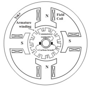 fig(A) sectional diagram of a D.C machines
Now let us examine how a D.C voltage is obtained across the brushes (armature terminals). Let us fix our attention to a particular position in space. Whichever conductor is present there right now, will have some definite induced voltage in it (dictated by e = b/v). In course of rotation of the armature newer conductors will occupy this position in space. No matter which conductor comes to that particular position at any given point of time, it will have same voltage induced in it. This is true for all the positions although the magnitude and polarity of the voltages in different position may be different. The polarity of the voltage is opposite for conductor positions under north or south pole. Remembering that all the conductors are connected in series and brushes are suitably placed for obtaining maximum voltage, the magnitude of the voltage across the brushes will remain constant.