Loop And Nodal Methods Of Analysis
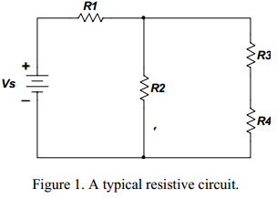
loop and nodal methods of analysis: We have seen that using Kirchhoff’s laws and Ohm’s law we can analyze any circuit to determine the operating conditions (the currents and voltages). The challenge of formal circuit analysis is to derive the smallest set of simultaneous equations that completely define the operating characteristics of a circuit. In this lecture we will develop two very powerful methods for analyzing any circuit: The node method and the mesh method. These methods are based on the systematic application of Kirchhoff’s laws. We will explain the steps required to obtain the solution by considering the circuit example shown on Figure 1.
Node Method: A voltage is always defined as the potential difference between two points. When we talk about the voltage at a certain point of a circuit we imply that the measurement is performed between that point and some other point in the circuit. In most cases that other point is referred to as ground. The node method or the node voltage method, is a very powerful approach for circuit analysis and it is based on the application of KCL, KVL and Ohm’s law. The procedure for analyzing a circuit with the node method is based on the following steps.
- Clearly label all circuit parameters and distinguish the unknown parameters from the known.
- Identify all nodes of the circuit.
- Select a node as the reference node also called the ground and assign to it a potential of 0 Volts. All other voltages in the circuit are measured with respect to the reference node.
- Label the voltages at all other nodes.
- Assign and label polarities.
- Apply KCL at each node and express the branch currents in terms of the node voltages.
- Solve the resulting simultaneous equations for the node voltages.
- Now that the node voltages are known, the branch currents may be obtained from Ohm’s law.
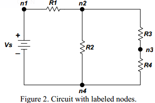
We will use the circuit of Figure 1 for a step by step demonstration of the node method. Figure 2 shows the implementation of steps 1 and 2. We have labeled all elements and
identified all relevant nodes in the circuit.
The third step is to select one of the identified nodes as the reference node. We have four different choices for the assignment. In principle any of these nodes may be selected as the reference node. However, some nodes are more useful than others. Useful nodes are the ones which make the problem easier to understand and solve. There are a few general guidelines that we need to remember as we make the selection of the reference node.
- A useful reference node is one which has the largest number of elements connected to it.
- A useful reference node is one which is connected to the maximum number of voltage sources.
For our example circuit the selection of node n4 as the reference node is the best choice. (equivalently we could have selected node n1 as our reference node.)
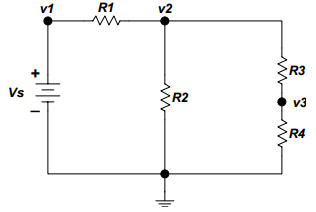
The next step is to label the voltages at the selected nodes. Figure 3 shows the circuit with the labeled nodal voltages. The reference node is assigned voltage 0 Volts indicated by the ground symbol. The remaining node voltages are labeled v1, v2, v3.
For the next step we assign current flow and polarities, see Figure 4.
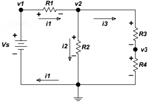 Figure 4. Example circuit with assigned node voltages and polarities.Before proceeding let’s look at the circuit shown on Figure 4 bit closer. Note that the problem is completely defined.