Phasor Representation Of Voltage And Current
Phasor representation of Voltage and Current: The voltage and current waveforms are given as:

It can be seen from the waveforms (Fig. b) of the two sinusoidal quantities – voltage and current, that the voltage, V lags the current I, which means that the positive maximum value of the voltage is reached earlier by an angle, φ , as compared to the positive maximum value of the current. In phasor notation as described earlier, the voltage and current are represented by OP and OQ (Fig. a) respectively, the length of which are proportional to voltage, V and current, I in different scales as applicable to each one. The voltage phasor, OP (V) lags the current phasor, OQ (I) by the angleφ , as two phasors rotate in the anticlockwise direction as stated earlier, whereas the angleφ is also measured in the anticlockwise direction. In other words, the current phasor (I) leads the voltage phasor (V).
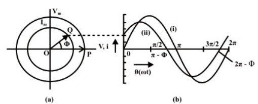
Mathematically, the two phasors can be represented in polar form, with the voltage
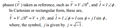
Of the two terms in each phasor, the first one is termed as real or its component in x-axis, while the second one is imaginary or its component in y-axis, as shown in Fig. (a). The angle,φ is in degree or rad.