Power Transmission And Distribution
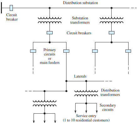
Power Transmission and Distribution: The structure of a power system can be divided into generation (G), transmission, (T), and distribution (D) facilities, as shown in Figure (A).An ac three-phase generating system provides the electric energy; this energy is transported over a transmission network, designed to carry power at high or extrahigh voltages over long distances from generators to bulk power substations and major load points; the subtransmission network is a medium to high-voltage network whose purpose is to transport power over shorter distances from bulk power substations to distribution substations. The transmission and subtransmission systems are meshed networks with multiplepath structure so that more than one path exists from one point to another to increase the reliability of the transmission system. The transmission system, in general, consists of overhead transmission lines (on transmission towers), transformers to step up or step down voltage levels, substations, and various protective devices such as circuit breakers, relays, and communication and control mechanisms. Figure A shows a typical electric-power distribution system and its components. Below the subtransmission level, starting with the distribution substation, the distribution system usually consists of distribution transformers, primary distribution lines or main feeders, lateral feeders, distribution transformers, secondary distribution circuits, and customers’ connections with metering. Depending on the size of their power demand, customers may be connected to the transmission system, the subtransmission system, or the primary or secondary distribution circuit.
 fig(A)Typical power-system structure.
In central business districts of large urban areas, the primary distribution circuits consist of underground cables which are used to interconnect the distribution transformers in an electric network. With this exception, the primary system is most often radial. However, for additional reliability and backup capability, a loop-radial configuration is frequently used. The main feeder is looped through the load area and brought back to the substation, and the two ends of the loop are connected to the substation by two separate circuit breakers. For normal operation, selected sectionalizing switches are opened so as to form a radial configuration. Under fault conditions, the faulted section is isolated and the rest of the loop is used to supply the unaffected customers.
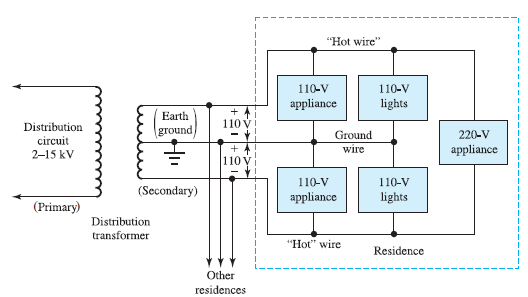
Most residences and small buildings are supplied with power by means of single-phase, three-wire service, as illustrated in Figure (B). A distribution transformer is located on a power pole or underground, near the residential customer. Inside residences, the 220-V supply, being available between the two “hot” wires, is used for major appliances such as dryers, ranges, and ovens. The 110-V loads up to 20 to 40 A are connected between the ground wire and either “hot” wire, while nearly balancing the loads on the two “hot” wires. Each of these circuits, protected by its own fuse or circuit breaker, supplies lighting loads and/or convenience outlets. In the wiring of residential and commercial buildings, safety considerations are of paramount importance, the principal hazards being fire and electric shock
 ..fig(B)