Principle Of Operation Of Three-phase Induction Motor

Principle of Operation of Three-phase Induction Motor: The balanced three-phase winding of the stator is supplied with a balanced three-phase voltage. the current in the stator winding produces a rotating magnetic field, the magnitude of which remains constant. The axis of the magnetic field rotates at a synchronous speed (ns=(2.f)/p) a function of the supply frequency (f), and number of poles (p) in the stator winding. The magnetic flux lines in the air gap cut both stator and rotor (being stationary, as the motor speed is zero) conductors at the same speed. The emfs in both stator and rotor conductors are induced at the same frequency, i.e. line or supply frequency, with No. of poles for both stator and rotor windings (assuming wound one) being same. The stator conductors are always stationary, with the frequency in the stator winding being same as line frequency. As the rotor winding is short-circuited at the slip-rings, current flows in the rotor windings. The electromagnetic torque in the motor is in the same direction as that of the rotating magnetic field, due to the interaction between the rotating flux produced in the air gap by the current in the stator winding, and the current in the rotor winding. This is as per Lenz’s law, as the developed torque is in such direction that it will oppose the cause, which results in the current flowing in the rotor winding. This is irrespective of the rotor type used − cage or wound one, with the cage rotor, with the bars short-circuited by two end-rings, is considered equivalent to a wound one The current in the rotor bars interacts with the air-gap flux to develop the torque, irrespective of the no. of poles for which the winding in the stator is designed. Thus, the cage rotor may be termed as universal one. The induced emf and the current in the rotor are due to the relative velocity between the rotor conductors and the rotating flux in the air-gap, which is maximum, when the rotor is stationary (nr=0.0). As the rotor starts rotating in the same direction, as that of the rotating magnetic field due to production of the torque as stated earlier, the relative velocity decreases, along with lower values of induced emf and current in the rotor. If the rotor speed is equal that of the rotating magnetic field, which is termed as synchronous speed, and also in the same direction, the relative velocity is zero, which causes both the induced emf and current in the rotor to be reduced to zero. Under this condition, torque will not be produced. So, for production of positive (motoring) torque, the rotor speed must always be lower than the synchronous speed. The rotor speed is never equal to the synchronous speed in an IM. The rotor speed is determined by the mechanical load on the shaft and the total rotor losses, mainly comprising of copper loss.
The difference between the synchronous speed and rotor speed, expressed as a ratio of the synchronous speed, is termed as ‘slip’ in an IM. So, slip (s) in pu is
 

fig.(A) production of torque


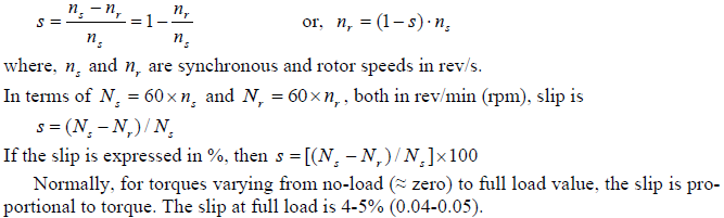
An alternative explanation for the production of torque in a three-phase induction motor is given here, using two rules (right hand and left hand) of Fleming. The stator and rotor, along with air-gap, is shown in Fig. A(a). Both stator and rotor is shown there as surfaces. This is for a section, which is under North pole, as the flux lines move from stator to rotor. The rotor conductor shown in the figure is at rest, i.e., zero speed (stand-still). The rotating magnetic field moves past the conductor at synchronous speed in the clockwise direction. Thus, there is relative movement between the flux and the rotor conductor. Now, if the magnetic field, which is rotating, is assumed to be at standstill as shown in Fig. A(b), the conductor will move in the direction shown. So, an emf is induced in the rotor conductor as per Faraday’s law, due to change in flux linkage. The direction of the induced emf as shown in the figure can be determined using Fleming’s right hand rule.
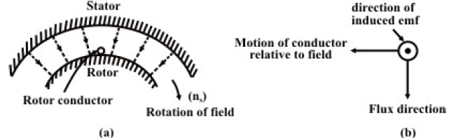
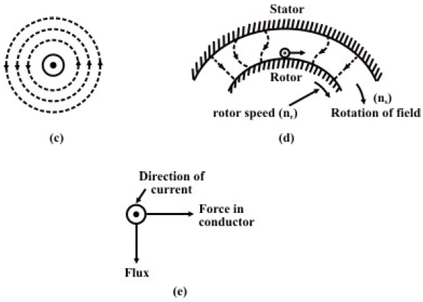
As described earlier, the rotor bars in the cage rotor are short circuited via end rings. Similarly, in the wound rotor, the rotor windings are normally short-circuited externally via the slip rings. In both cases, as emf is induced in the rotor conductor (bar), current flows there, as it is short circuited. The flux in the air gap, due to the current in the rotor conductor is shown in Fig. A(c). The flux pattern in the air gap, due to the magnetic fields produced by the stator windings and the current carrying rotor conductor, is shown in Fig. A(d). The flux lines bend as shown there. The property of the flux lines is to travel via shortest path as shown in Fig. A(a). If the flux lines try to move to form straight line, then the rotor conductor has to move in the direction of the rotating magnetic field, but not at the same speed, as explained earlier. The current carrying rotor conductor and the direction of flux are shown in Fig. A(e). It is known that force is produced on the conductor carrying current, when it is placed in a magnetic field. The direction of the force on the rotor conductor is obtained by using Fleming’s left hand rule, being same as that of the rotating magnetic field. Thus, the rotor experiences a motoring torque in the same direction as that of the rotating magnetic field. This briefly describes how torque is produced in a three-phase induction motor.