Series Resistor-inductor Circuits: Impedance
Series resistor-inductor circuits: Now we will mix the two components together in series form and investigate the effects.
Take this circuit as an example to work with: (Figure below)
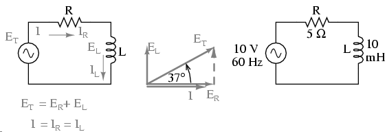
Series resistor inductor circuit: Current lags applied voltage by 0o to 90o.
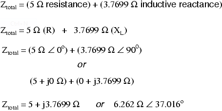
The resistor will offer 5 Ω of resistance to AC current regardless of frequency, while the inductor will offer 3.7699 Ω of reactance to AC current at 60 Hz. Because the resistor's resistance is a real number (5 Ω ∠ 0o, or 5 j0 Ω), and the inductor's reactance is an imaginary number (3.7699 Ω ∠ 90o, or 0 j3.7699 Ω), the combined effect of the two components will be an opposition to current equal to the complex sum of the two numbers. This combined opposition will be a vector combination of resistance and reactance. In order to express this opposition succinctly, we need a more comprehensive term for opposition to current than either resistance or reactance alone. This term is called impedance, its symbol is Z, and it is also expressed in the unit of ohms, just like resistance and reactance. In the above example, the total circuit impedance is:
Impedance is related to voltage and current just as you might expect, in a manner similar to resistance in Ohm's Law:
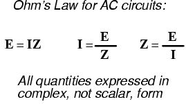
In fact, this is a far more comprehensive form of Ohm's Law than what was taught in DC electronics (E=IR), just as impedance is a far more comprehensive expression of opposition to the flow of electrons than resistance is. Any resistance and any reactance, separately or in combination (series/parallel), can be and should be represented as a single impedance in an AC circuit.
To calculate current in the above circuit, we first need to give a phase angle reference for the voltage source, which is generally assumed to be zero. (The phase angles of resistive and inductive impedance are always 0o and 90o, respectively, regardless of the given phase angles for voltage or current).
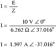
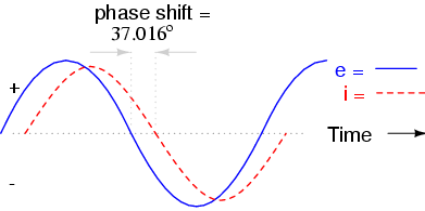
As with the purely inductive circuit, the current wave lags behind the voltage wave (of the source), although this time the lag is not as great: only 37.016o as opposed to a full 90o as was the case in the purely inductive circuit. (Figure below)