Shunts And Multipliers For Mi Instruments
Shunts and Multipliers for MI instruments: For moving-iron ammeters: For the circuit shown in Fig.), let Rm and Lmare respectively the resistance and inductance of the coil and Rsh and Lsh the corresponding values for shunt.
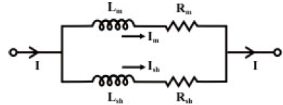 fig.(A)
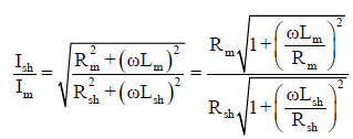
The ratio of currents in two parallel branches is
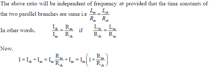
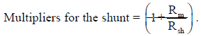
It is difficult to design a shunt with the appropriate inductance, and shunts are rarely incorporated in moving iron ammeters. Thus the multiple ranges can effectively be obtained by winding the instrument coil in sections which may be connected in series, parallel or series-parallel combination which in turn changing the total ampere-turns in the magnetizing coil.
For moving-iron voltmeters: Voltmeter range may be altered connecting a resistance in series with the coil. Hence the same coil winding specification may be employed for a number of ranges. Let us consider a high resistance Rse is connected in series with the moving coil and it is shown below.
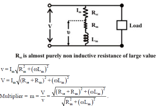
Note: An ordinary arrangement with a non-inductive resistance in series with the fixed coil – results in error that increases as the frequency increases. The change of impedance of the instrument with change of frequency introduces error in signal measurements. In order to compensate the frequency error, the multiplier may be easily shunted by the capacitor.
Advantages:
• The instruments are suitable for use in a.c and d.c circuits.
• The instruments are robust, owing to the simple construction of the moving parts.
• The stationary parts of the instruments are also simple.
• Instrument is low cost compared to moving coil instrument.
• Torque/weight ration is high, thus less frictional error.