←
Basic Electrical Engineering
Simple Series Resonance
Simple series resonance: A similar effect happens in series inductive/capacitive circuits. When a state of resonance is reached (capacitive and inductive reactances equal), the two impedances cancel each other out and the total impedance drops to zero!
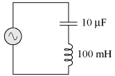
At 159.155 Hz the following values are valid:
ZL = 0 j100 Ω
ZC = 0 - j100 Ω
Zseries = ZC ZL
Zseries = 0 - j100 Ω 0 j100 Ω = 0 Ω
With the total series impedance equal to 0 Ω at the resonant frequency of 159.155 Hz, the result is a short circuit across the AC power source at resonance. In the circuit drawn above, this would not be good. I'll add a small resistor in series along with the capacitor and the inductor to keep the maximum circuit current somewhat limited.
| Review |
|