Source Transformation
Source Transformation: In an electric circuit, it is often convenient to have a voltage source rather than a current source (e.g. in mesh analysis) or vice versa. This is made possible using source transformations. It should be noted that only practical voltage and current sources can be transformed. In other words, a Th´evenin’s equivalent circuit is transformed into a Norton’s one or vice versa. The parameters used in the source transformation are given as follows.

Any load resistance, RL will have the same voltage across, and current through it when connected across the terminals of either source.
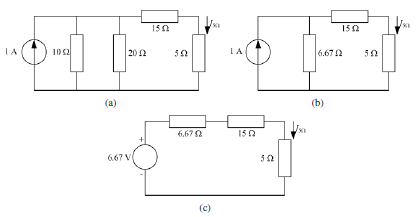
Example: In given figure, use repeated source transformation to determine the current through the5Ωresistance. Noting that the voltage source and the 10 Ω resistor are in series, transform the combination into a current source in parallel with the 10 Ω resistor. The magnitude of the current source is calculated as
follows

![]()
The resulting schematic is depicted in Figure(a). Now the 10 Ω and 20 Ω resistors are in parallel which can be combined together to form a single resistance of 6.67 Ω (see Figure (b)). This resistance will be in parallel with the 1 A current source that can be transformed back to a voltage source in series with the 6.67 Ω resistance resulting in single loop as shown in Figure(c). KVL can be applied to determine the loop current which is the same current flowing through the 5 Ω resistor. Hence


repeated source transfoemation of given figure