Starting Current And Torque
Starting Current and Torque:
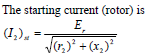
as slip at starting (nr= 0.0) is 1.0,which is the same at standstill (or stalling condition). The magnitude of the induced voltage per phase in the stator winding is nearly same as input voltage per phase fed to the stator, if the voltage drop in the stator impedance, being small, is neglected, i.e. Vs≈Vs, the ratio of the induced emfs per phase in the stator and rotor winding can be taken as the ratio of the effective turns in two windings, i.e. Es/Er= ts' =kwsTs and Tr' = kwrTr. The winding factor for the stator winding is kws = kds•kps. Same formula is used for the above factor in the rotor winding, assuming it to be wound rotor one.
Same formula is used for the above factor in the rotor winding, assuming it to be wound rotor one. (Is)st = (Ir)st•(Tr'/Ts'), neglecting the no load current. This current is normally large, much greater than full load current. This current is reduced by using starters in both types (cage and wound rotor) of IM, which will be taken up in the next lesson.
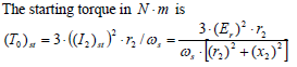
This expression is obtained substituting s = 1.0 in the expression of To derived earlier. If the starter is used, the starting torque is also reduced, as is the case with starting current.
Torque-slip (speed) Characteristics,
with variation in input (stator) voltage and rotor circuit resistance
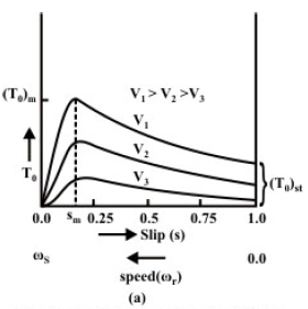 fig(A)torque-speed characterstics for vairiation in input(stator )voltage
The set of torque-slip characteristics with variation in input (stator) voltage is shown in Fig. (A). The point to note that the torque at a given slip decreases with the decrease in input (stator) voltage, as T0∝V2 . The characteristics shown are for decreasing stator voltages (V1>V2>V3). The speed decreases or the slip increases with constant load torque, as the input (stator) voltage decreases. The region for stable operation with constant load torque remains same (0.0<s<sm), as given earlier. But again, stable operation can be obtained in the region (sm<s<1.0), with fan type loads with the torque as (TL∝(nr)2). Another problem is that the maximum or pull-out torque decreases as (To)m∝ V2, where V is input (stator) voltage, which is a drawback with constant load torque operation..
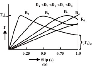 The set of torque-slip characteristics with variation in rotor circuit resistance is shown in Fig. (B). The characteristics shown are for increasing rotor circuit resistances (). The point to note that, the maximum torque remains same for all the characteristics. This has been shown earlier that the maximum torque depends on rotor reactance only, but not on rotor circuit resistance. Only the slip at maximum torque increases with the increase in rotor circuit resistance. So, for constant load torque operation, the slip increases or the speed decreases with the increase in rotor circuit resistance. The motor efficiency decreases, as the rotor copper loss increases with the increase in slip. The load torque remains same, but the output power decreases, as the speed decreases. Also, it may be observed that the starting torque increases with the increase in rotor circuit resistance, with the total rotor circuit resistance lower than rotor reactance. The starting torque is equal to the maximum torque, when the total rotor circuit resistance is equal to rotor reactance. If the rotor circuit resistance is more than rotor reactance, the starting torque decreases.
fig(B) variation in total rotor circuit resistance.