A Servo System
A servo system:

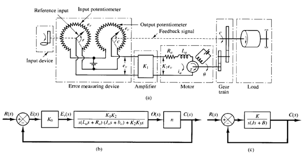
Fig: 1 (a) Schematic diagram of servo system; (b) block diagram for the system; (c) simplified block diagram.
Consider the servo system shown in Figure 1(a). The objective of this system is to control the position of the mechanical load in accordance with the reference position. The operation of this system is as follows: A pair of potentiometers acts as an error-measuring device. They convert the input and output positions into proportional electric signals. The command input signal determines the angular position r of the wiper arm of the input potentiometer. The angular position r is the reference input to the system, and the electric potential of the arm is proportional to the angular position of the arm. The output shaft position determines the angular position c of the wiper arm of the output potentiometer. The difference between the input angular position r and the output angular position c is the error signal e, or

The potential difference er - ec = ev is the error voltage, where er is proportional to r and ec is proportional to c; that is, er = K0r and ec = K0c, where K0 is a proportionality constant. The error voltage that appears at the potentiometer terminals is amplified by the amplifier whose gain constant is K1. The output voltage of this amplifier is applied to the armature circuit of the dc motor. (The amplifier must have very high input impedance because the potentiometers are essentially high impedance circuits and do not tolerate current drain. At the same time, the amplifier must have low output impedance since it feeds into the armature circuit of the motor.) A fixed voltage is applied to the field winding. If an error exists, the motor develops a torque to rotate the output load in such a way as to reduce the error to zero. For constant field current, the torque developed by the motor is

where K2 is the motor torque constant and ia is the armature current. Notice that if the sign of the current ia is reversed the sign of the torque Twill be reversed, which will result in the reversion of the direction of rotor rotation. When the armature is rotating, a voltage proportional to the product of the flux and angular velocity is induced in the armature. For a constant flux, the induced voltage eb is directly proportional to the angular velocity dθ/dt, or

where eb is the back emf, K3 is the back emf constant of the motor, and θ is the angular displacement of the motor shaft.
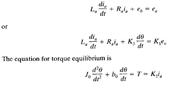
The speed of an armature-controlled dc servomotor is controlled by the armature voltage ea. (The armature voltage ea = K1ev is the output of the amplifier.) The differential equation for the armature circuit is

where J0 is the inertia of the combination of the motor, load, and gear train referred to the motor shaft and bo is the viscous-friction coefficient of the combination of the motor, load, and gear train referred to the motor shaft.