Block Diagram Of A Closed-loop System
Block diagram of a closed-loop system:

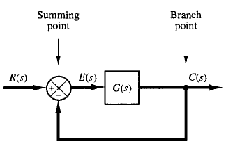
Fig: 1 Block diagram of a closed-loop system.
Figure 1 shows an example of a block diagram of a closed-loop system. The output C(s) is fed back to the summing point, where it is compared with the reference input R(s). The closed-loop nature of the system is clearly indicated by the figure. The output of the block, C(s) in this case, is obtained by multiplying the transfer function G(s) by the input to the block, E(s). Any linear control system may be represented by a block diagram consisting of blocks, summing points, and branch points.
When the output is fed back to the summing point for comparison with the input, it is necessary to convert the form of the output signal to that of the input signal. For example, in a temperature-control system, the output signal is usually the controlled temperature.

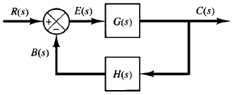
Fig: 2 Closed-loop system
The output signal, which has the dimension of temperature, must be converted to a force or position or voltage before it can be compared with the input signal. This conversion is accomplished by the feedback element whose transfer function is H(s), as shown in Figure 2.
The role of the feedback element is to modify the output before it is compared with the input. (In most cases the feedback element is a sensor that measures the output of the plant. The output of the sensor is compared with the input, and the actuating error signal is generated.) In the present example, the feedback signal that is fed back to the summing point for comparison with the input is B(s) = H(s)C(s).