Servo System With Velocity Feedback.
Servo system with velocity feedback:
The derivative of the output signal can be used to improve system performance. In obtaining the derivative of the output position signal, it is desirable to use a tachometer instead of physically differentiating the output signal. (Note that the differentiation amplifies noise effects. In fact, if discontinuous noises are present, differentiation amplifies the discontinuous noises more than the useful signal.
For example, the output of a potentiometer is a discontinuous voltage signal because, as the potentiometer brush is moving on the windings, voltages are induced in the switchover turns and thus generate transients. The output of the potentiometer therefore should not be followed by a differentiating element.)
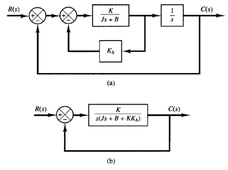
Fig: (a) Block diagram of a servo system; (b) simplified block diagram.
Consider the servo system shown in Figure 1(a). In this device, the velocity signal, together with the positional signal, is fed back to the input to produce the actuating error signal. In any servo system, such a velocity signal can be easily generated by a tachometer. The block diagram shown in Figure 1(a) can be simplified, as shown in Figure 1(b), giving
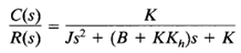
Comparing the above equation with
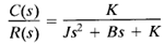
We notice that the velocity feedback has the effect of increasing damping. The damping ratio  becomes

The undamped natural frequency  is not affected by velocity feedback. Noting that the maximum overshoot for a unit-step input can be controlled by controlling the value of the damping ratio , we can reduce the maximum overshoot by adjusting the velocity feedback constant Kh so that is between 0.4 and 0.7.
Remember that velocity feedback has the effect of increasing the damping ratio without affecting the undamped natural frequency of the system.