Signal-flow Graph Models
Signal-flow graph models
Block diagrams are adequate for the representation of the interrelationships of controlled and input variables. However, for a system with reasonably complex interrelationships, the block diagram reduction procedure is cumbersome and often quite difficult to complete. An alternative method for determining the relationship between system variables has been developed by Mason and is based on a representation of the system by line segments. The advantage of the line path method, called the signal-flow graph method, is the availability of a flow graph gain formula, which provides the relation between system variables without requiring any reduction procedure or manipulation of the flow graph.


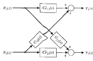
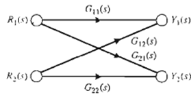
Fig: 1 Fig: 2
The transition from a block diagram representation to a directed line segment representation is easy to accomplish by reconsidering the systems in block diagrams. A signal-flow graph is a diagram consisting of nodes that are connected by several directed branches and is a graphical representation of a set of linear relations. Signal-flow graphs are particularly useful for feedback control systems because feedback theory is primarily concerned with the flow and processing of signals in systems.
The basic element of a signal-flow graph is a unidirectional path segment called a branch, which relates the dependency of an input and an output variable in a manner equivalent to a block of a block diagram. Therefore, the branch relating the output θ(s) of a DC motor to the field voltage Vf(s) is similar to the block diagram of Figure 1 and is shown in Figure 2. The input and output points or junctions are called nodes. Similarly, the signal-flow graph representing Equations


Fig: 3 Fig: 4
as well as Figure 3, is shown in Figure 4. The relation between each variable is written next to the directional arrow. All branches leaving a node will pass the nodal signal to the output node of each branch (uni-directionally). The summation of all signals entering a node is equal to the node variable. A path is a branch or a continuous sequence of branches that can be traversed from one signal (node) to another signal (node). A loop is a closed path that originates and terminates on the same node, with no node being met twice along the path. Two loops are said to be non-touching if they do not have a common node. Two touching loops share one or more common nodes. Therefore, considering Figure 3 again, we obtain

The flow graph is simply a pictorial method of writing a system of algebraic equations that indicates the interdependencies of the variables. As another example consider the following set of simultaneous algebraic equations:
