←
Control Systems - 1
Transfer Function Of An Armature-controlled Motor
Transfer function of an armature-controlled motor

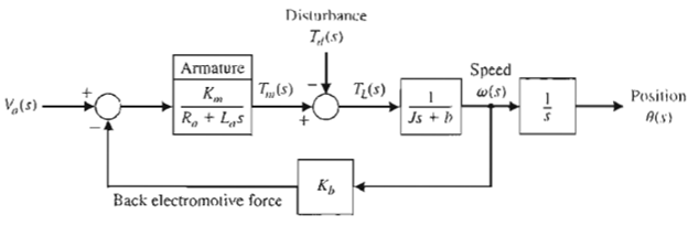
Fig: 1 Block diagram of armature controlled motor

Fig: 2
The block diagram of the armature-controlled DC motor is shown in Figure 1. The signal-flow diagram can be obtained from the block diagram and is shown in Figure 2. Using Mason's signal-flow gain formula, let us obtain the transfer function for θ(s)/Va(s) with Td(s) = 0. The forward path is P1(s), which touches the one loop, L1(s), where

Therefore, the transfer function is

which is exactly the same as that from the block diagram.