Efficient Fft Implementations
Efficient FFT implementations
Since the practical applications of the DFT, such as signal processing, demand the utmost speed, this section examines two efficient FFT implementations. First, we shall examine an iterative version of the FFT algorithm that runs in Θ(n lg n) time but has a lower constant hidden in the Θ-notation than the recursive implementation in DFT and FFT. Then, we shall use the insights that led us to the iterative implementation to design an efficient parallel FFT circuit.
An iterative FFT implementation
We first note that the for loop of lines 10 -13 of RECURSIVE-FFT involves computing the value  twice. In compiler terminology, this value is known as a common subexpression. We can change the loop to compute it only once, storing it in a temporary variable t.
		for k ← 0 to n/2 - 1
          do

The operation in this loop, multiplying the twiddle factor  by
by  , storing the product into t, and adding and subtracting t from
  , is known as a butterfly operation and is shown schematically in Figure 30.3.

Figure 30.3: A butterfly operation. (a) The two input values enter from the left, the twiddle factor
 is multiplied by
  , and the sum and difference are output on the right. (b) A simplified drawing of a butterfly operation. We will use this representation in a parallel FFT circuit.
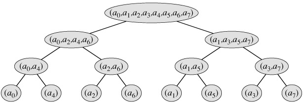
We now show how to make the FFT algorithm iterative rather than recursive in structure. In Figure 30.4, we have arranged the input vectors to the recursive calls in an invocation of RECURSIVE-FFT in a tree structure, where the initial call is for n = 8. The tree has one node for each call of the procedure, labeled by the corresponding input vector. Each RECURSIVE-FFT invocation makes two recursive calls, unless it has received a 1-element vector. We make the first call the left child and the second call the right child.

Figure 30.4: The tree of input vectors to the recursive calls of the RECURSIVE-FFT procedure. The initial invocation is for n = 8.
Looking at the tree, we observe that if we could arrange the elements of the initial vector a into the order in which they appear in the leaves, we could mimic the execution of the RECURSIVE-FFT procedure as follows. First, we take the elements in pairs, compute the DFT of each pair using one butterfly operation, and replace the pair with its DFT. The vector then holds n/2 2-element DFT's. Next, we take these n/2 DFT's in pairs and compute the DFT of the four vector elements they come from by executing two butterfly operations, replacing two 2-element DFT's with one 4-element DFT. The vector then holds n/4 4-element DFT's. We continue in this manner until the vector holds two (n/2)-element DFT's, which we can combine using n/2 butterfly operations into the final n-element DFT.
To turn this observation into code, we use an array A[0 ‥n - 1] that initially holds the elements of the input vector a in the order in which they appear in the leaves of the tree of Figure 30.4. (We shall show later how to determine this order, which is known as a bit-reversal permutation.) Because the combining has to be done on each level of the tree, we introduce a variable s to count the levels, ranging from 1 (at the bottom, when we are combining pairs to form 2-element DFT's) to lg n (at the top, when we are combining two (n/2)-element DFT's to produce the final result). The algorithm therefore has the following structure:
		1   for s ← 1 to lg n
2        do for k ← 0 to n - 1 by 2s
3               do combine the two 2s-1-element DFT's in
                     A[k ‥k   2s-1 - 1] and A[k   2s-1 ‥k   2s - 1]
                     into one 2s-element DFT in A[k ‥k   2s - 1]
We can express the body of the loop (line 3) as more precise pseudocode. We copy the for loop from the RECURSIVE-FFT procedure, identifying y[0] with A[k ‥ k 2s-1 - 1] and y[1] with A[k 2s-1 ‥k 2s - 1]. The twiddle factor used in each butterfly operation depends on the value of s; it is a power of wm, where m = 2s. (We introduce the variable m solely for the sake of readability.) We introduce another temporary variable u that allows us to perform the butterfly operation in place. When we replace line 3 of the overall structure by the loop body, we get the following pseudocode, which forms the basis of the parallel implementation we shall present later. The code first calls the auxiliary procedure BIT-REVERSE-COPY (a, A) to copy vector a into array A in the initial order in which we need the values.