The Labeling Algorithm
The labeling algorithm
Step 1 : Let N1 be the set of all nodes connected in the source by an edge with positive excess capacity. Label each j in N1 with [Ej, 1], where Ej is the excess capacity e1j of edge (1, j). The 1 in the label indicates that j is connected to the source, node 1.
Step 2 : Let node j in N1 be the node with smallest node number and let N2 (j) be the set of all unlabeled nodes, other than the source, that are joined to node j and have positive excess capacity.
Suppose that node k is in N2 (j) and (j, k) is the edge with positive excess capactiy. Label node k with [Ek, j], where Ek is the minimum of Ej and the excess capacity ejk of edge (j, k).
When all the nodes in N2 (j) are labeled in this way, repeat this process for the other nodes in N1.
![]()
Note that after step 1, we have labeled each node j in N1 with Ej, the amount of material that can flow from the source to j through one edge and with the information that this flow came from node 1. In step 2, previously unlabeled nodes k that can be reached from the source by a path π : 1, j, k are labeled with [Ek, j].
Here Ek is the maximum flow that can pass through π since it is the smaller of the amount that can reach j and the amount that can then pass on to k. Thus, when step 2, is finished, we have constructed two-step paths to all nodes in N2. The label for each of these nodes records the total flow that can reach the node through the path and its immediate predecessor in the path.
We attempt to continue this construction increasing the lengths of the paths until we reach the sink (if possible).
Then the total flow can be increased and we can retrace the path used for this increase.
Step 3 : Repeat step 2, labelling all previously unlabeled nodes N3 that can be reached from a node in N2 by an edge having positive excess capacity. Continue this process forming sets N4, N5, .... until after a finite number of steps either
(i) The sink has not been labeled and no other nodes can be labeled. It can happen that no nodes have been labeled, remember that the source is not labeled. or
(ii) The sink has been labeled.
Step 4 : In case (i), the algorithm terminates and the total flow then is a maximum flow.
Step 5 : In case (ii) the sink, node n, has been labeled with [En, m] where En is the amount of extra flow that can be made to reach the sink through a path π. We examine π in reverse order. If each (i, j) ∈ N, then we increase the flow in (i, j) by En and decrease the excess capacity eij by the same amount.
Simultaneously, we increase the excess capacity of the (virtual) edge (j, i) by En since there is that much more flow in (i, j) to reverse.
If on the other hand, (i, j) ∉ N, we decrease the flow in (j, i) by En and increase its excess capacity by En.
We simultaneously decrease the excess capacity in (i, j) by the same amount, since there is less flow in (i, j) to reverse.
We now have a new flow that is En units greater than before and we return to step 1.
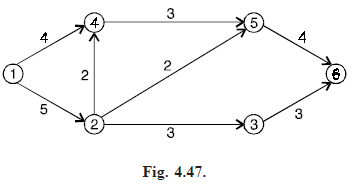
Problem . Use the labeling algorithm to find a maximum flow for the network in Fig. (4.47).

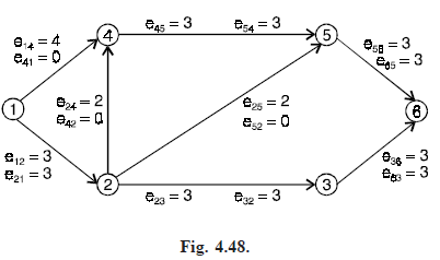
Solution. Fig. (4.48) shows the network with initial capacities of all edges in G. The initial flow in all edges is zero.

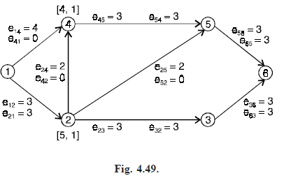
Step 1 : Starting at the source, we can reach nodes 2 and 4 by edges having excess capacity, so N1 = {2, 4}. We label nodes 2 and 4 with the labels [5, 1] and [4, 1], respectively, as shown in Fig. (4.49).
