Force Causality Issues
Force-Motion Causality
The response of a mechanical control system does not necessarily have to be a motion variable. When the objective of a control system is to produce a desired motion, the response variables (outputs) are the associated motion variables.
A good example is the response of a spray-painting robot whose end effector is expected to follow a specific trajectory of motion.
On the other hand, when the objective is to exert a desired set of forces (or torques)—which is the case in some tasks of machining, forging, gripping, engraving, and assembly—the outputs are the associated force variables.
The choice of inputs and outputs cannot be done arbitrarily, however, for a physical system.
The conditions of “physical reliability” have to be satisfied, as we will illustrate.
A lumped-parameter mechanical system can be treated as a set of basic mechanical elements (springs, inertia elements, dampers, levers, gyros, force sources, and velocity sources, etc.) that are interconnected through ports (or bonds) through which power (or energy) flows.
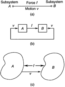
Each port actually consists of two terminals. There is an effort variable (force) f and a flow variable (motion, such as velocity) u associated with each port. In particular, consider a port that connects two subsystems A and B.
The two subsystems interact, and power flows through the port. Hence, for example, if we assume that A pushes B with a force f, then f is considered input to B. Now, B responds with motion u—the output of B—which, in turn causes A to respond with force f.
This cause effect relationship (causality) is clearly shown by the block diagram representation. A similar argument would lead to the opposite causality if we had started with the assumption that B is pushing A with force f.
It follows that one has to make some causal decisions for a dynamic system, based on system requirements and physical reliability, and the rest of the causalities will be decided automatically.
It can be shown that conflicts in causality indicate that the energy storage elements (e.g., springs, masses) in the particular system model are not independent. Note that causality is not governed by the positive direction assigned to the variables f and u.
This is clear from the free-body diagram representation in Figure 6.35(c). In particular, if the force f on A (the action) is taken as positive in one direction, and then according to Newton’s third law, the force f on B (the reaction) is positive in the opposite direction. Similarly, if the velocity u of B relative to A is positive in one direction, then the velocity u of A relative to B is positive in the opposite direction. These directions are unrelated to the input/output (causality) directions. The above discussion shows that forces can be considered outputs (responses) as well as inputs (excitations), depending on the functional requirements of a particular system. In particular, when force is considered

Force-motion causality: (a) Bond or port representation; (b) Block diagram representation; (c) Free-body
diagram representation.