Magnetic Encoder
Introduction:
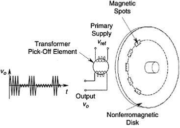
This signal can be interpreted in the usual manner. Note that a pulse peak corresponds to a nonmagnetic area and a pulse valley corresponds to a magnetic area on each track. Magnetic encoders have noncontacting pick-off sensors, which is an advantage.
They are more costly than them contacting devices, however, primarily because of the cost of transformer elements and demodulating circuitry for generating the output signal.
Schematic representation of a magnetic encoder. however, thereby significantly increasing the reluctance and dropping the induced voltage. By demodulating the induced voltage, a pulse signal is obtained.

Proximity sensor encoders use a proximity sensor as the signal pick-off element. Any type of proximity sensor may be used—for example, a magnetic induction probe or an eddy current probe. In the magnetic induction probe, for example, the disk is made of ferromagnetic material.
The encoder tracks have raised spots of the same material, serving a purpose analogous to that of the windows on an optical encoder disk. As a raised spot approaches the probe, the flux linkage increases as a result of the associated decrease in reluctance, thereby raising the induced voltage level.
The output voltage is a pulse-modulated signal at the frequency of the supply (primary) voltage of the proximity sensor. This is then demodulated, and the resulting pulse signal is interpreted. Instead of a disk with a track of raised regions, a ferromagnetic toothed wheel may be used along with a proximity sensor placed in a radial orientation. In principle, this device operates like a conventional digital tachometer. If an eddy current probe is used, pulse areas in the track have to be plated with a conducting material.
Furthermore, the windows in a track are not equally spaced but are arranged in a specific pattern so as to obtain a binary code (or a gray code) for the output data from the transducer. It follows those absolute encoders need at least as many signal pick-off sensors as there are tracks, whereas incremental encoders need one pickoff sensor to detect the magnitude of rotation. As will be explained, it will also need a sensor at a quarter-pitch separation (pitch=center-to-center distance between adjacent windows) to generate a quadrature signal, which will identify the direction of rotation.
Some designs of incremental encoders have two identical tracks, one at a quarter-pitch offset from the other, and the two pick-off sensors are placed radially without offset. The two (quadrature) signals obtained with this arrangement will be similar to those with the previous arrangement. A pick-off sensor for receiving a reference pulse is also used in some designs of incremental encoders (three-track incremental encoders).