Output Signals Of A Mechatronic System
Output Signals of a Mechatronic System DIGITAL-TO-ANALOG CONVERTERS:
The output command from the microcontroller is a binary value in bit, byte (8 bits), or word (16 bits) form. This digital signal is converted to analog using a digital-to-analog converter, or DAC.
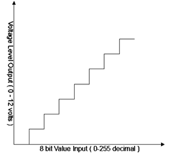
Let us examine converting an 8-bit value into a voltage level between 0 and 12 V. The most significant bit in the binary value to be converted (decimal 128) creates an analog value equal to half of the maximum output, or 6 V.
The next digit produces an additional one fourth, or 3 V, the next an additional one eighth, and so forth. The sum of all these weighted output values represents the appropriate analog voltage. As was mentioned in a previous section, the maximum voltage value in the range is not obtainable, as the largest value\ generated is 255/256 of 12 V, or 11.953125 V.
The smoothness of the signal representation depends on the number of bids accepted by the DAC and the range of the output required.

DAC stepped output

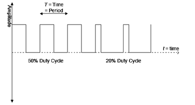
Pulse width modulation
Actuator Output
The three common actuatorsthat this section will review are switches, solenoids, and motors. Switches are simple state devices that control some activity, like turning on and off the furnace in a house.
Types of switches include relays and solid-state devices. Solid-state devices include diodes, Thyristor, bipolar transistors, field-effect transistors (FETs), and metal-oxide field-effect transistors (MOSFETs). A switch can also be used with a sensor, thus turning on or off the entire sensor, or a particular feature of a sensor. Solenoids are devices containing a movable iron core that is activated by a current flow. The movement of this core can then control some form of hydraulic or pneumatic flow. Applications are many, including braking systems and industrial production of fluids.
More information on solenoid actuators can be found in a later chapter.
There are three main types:direct current (DC), alternating current (AC), and stepper motors.
a) DC motorsmay be controlled by a fixed DC voltage or by pulse width modulation (PWM). In a PWM signal, a voltage is alternately turned on and off while changing (modulating) the width of the on-time signal, or duty cycle.
b) AC motorsare generally cheaper than DC motors, but require variable frequency drive to control the rotational speed.
c) Stepper motorsmove by rotating a certain number of degrees in response to an input pulse.