Resolver
Introduction:
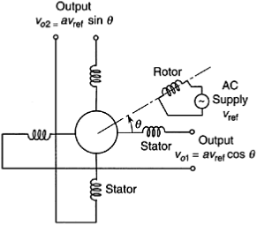
This mutual-induction transducer is widely used for measuring angular displacements. A simplified schematic diagram of the resolver.
Resolver:
The rotor contains the primary coil. It consists of a single two pole winding element energized by an ac supply voltage uref. The rotor is directly attached to the object whose rotation is being measured.
The stator consists of two sets of windings placed 90° apart.
If the angular position of the rotor with respect to one pair of stator windings is denoted by q, the induced voltage in this pair of windings is given by
u01=auref cos q
The induced voltage in the other pair of windings is given by
uo2=auref sin q

90°-q (i.e., a positive rotation and a negative rotation from the 90° position), but the corresponding cosine values have opposite signs, thus providing the proper direction.