Engineering Applications Of Interference Phenomenon
Engineering applications of Interference phenomenon: While discussing various methods of producing interference fringes, we discussed how these can be used to determine the wavelength of monochromatic light, the separation between the two closely spaced wavelengths, thickness and refractive index of thin transparent sheet and refractive index of a liquid.
Apart from these, interference phenomenon finds many interesting engineering applications. These include testing of flatness of optical surfaces, the angle of beam splitter, testing of prism and lens for chromatic aberrations,, measurement of thickness of a thin film, collimation testing, measurement of angle of a wedge etc. We shall discuss a few in the following.
Testing of optical surfaces –The optical surfaces are tested either by contact method where the test surface is put in contact with the master surface (an experimental arrangement similar to Newton's ring method) or by inserting the test surface in the path of two beams (experimental arrangement is similar to Michelson interferometer) and is known as Twyman-Green interferometer)
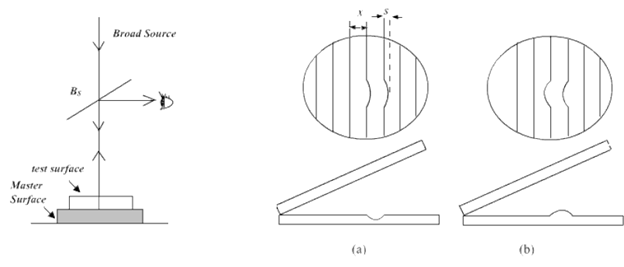
Contact method : In the contact method (Fig.A), the test surface is placed in contact with the master surface with a tissue paper in between them. The tissue paper is then pulled out slowly. The two surfaces are now in contact with each other with a small wedge angle between them. If test surface does not depart significantly from flat surface, a fringe system is observed with slight distortion at the points where surface is not smooth. (FigB). The flatness is given by ![]() where s is the amount by which the fringe is shifted, x is the fringe width and
where s is the amount by which the fringe is shifted, x is the fringe width and ![]() is the wavelength of light used. If surface departs considerably from flatness but is of regular shape (such as concave or convex lens), a circular fringe pattern is observed. By changing the direction of viewing one can find if the surface is concave or convex. If the fringes move inward when the angle of viewing is increased, the surface is concave. If there are N circular fringes, the surface departs from flatness by
is the wavelength of light used. If surface departs considerably from flatness but is of regular shape (such as concave or convex lens), a circular fringe pattern is observed. By changing the direction of viewing one can find if the surface is concave or convex. If the fringes move inward when the angle of viewing is increased, the surface is concave. If there are N circular fringes, the surface departs from flatness by ![]() and has a radius of curvature
and has a radius of curvature ![]() where ‘2d ' is diameter over which N fringes are observed.
where ‘2d ' is diameter over which N fringes are observed.

Fig. A:An Arrangement for testing optical source Fig.B:Fringe Pattern (a)Surface having dip (b) Bump