Retardation Plate
Retardation Plate: The retardation plate or the phase shifter is an optical component which can rotate or modify the plane of polarization of the incident beam falling on to it. In its simplest form, the retardation plate consists of a uniaxial crystal cut in such a way that the the optics axis or symmetry axis lies in the plane of the plate. If a retardation plates introduces a phase change of ![]() or
or ![]() (p being an integer) in the two mutually orthogonal components of electric field associated with the light wave then it is called as half wave plate . As in such case the relative path difference introduced in the two components is
(p being an integer) in the two mutually orthogonal components of electric field associated with the light wave then it is called as half wave plate . As in such case the relative path difference introduced in the two components is ![]() or half the wavelength. If the corresponding phase difference introduced is
or half the wavelength. If the corresponding phase difference introduced is![]() or
or ![]() , then it is called as quarter wave plate as in this situation the relative path difference introduced is
, then it is called as quarter wave plate as in this situation the relative path difference introduced is ![]() . With in the retardation plate, the optics axis and the axis normal to it are called as slow axis and the fast axis. The slow axis will be the axis for which refractive index is large and the fast axis is the axis for which the refractive index is small and hence the speed of propagation will be small in former and large in later case. Let us consider a half wave plate such that optics axis is making an angle of
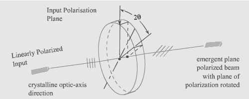
. With in the retardation plate, the optics axis and the axis normal to it are called as slow axis and the fast axis. The slow axis will be the axis for which refractive index is large and the fast axis is the axis for which the refractive index is small and hence the speed of propagation will be small in former and large in later case. Let us consider a half wave plate such that optics axis is making an angle of ![]() with the y axis and is placed in y-z plane. A linearly polarized plane wave is allowed to fall at normal incidence on this wave plate as shown in Fig 1. The direction of propagation of this wave is along x axis.The wave is polarized along y direction and its electric field
with the y axis and is placed in y-z plane. A linearly polarized plane wave is allowed to fall at normal incidence on this wave plate as shown in Fig 1. The direction of propagation of this wave is along x axis.The wave is polarized along y direction and its electric field ![]() can be represented as
can be represented as
![]() (1)
(1)

Fig 1: Half wave plate
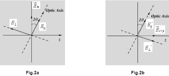
This field can be resolved into two components; E|| , along the optics axis and ![]() , perpendicular to the optics axis as shown in Fig 2a .
, perpendicular to the optics axis as shown in Fig 2a .

Both these components are given by
![]() (2)
(2)
![]() (3)
(3)
if the thickness of the half plate is L then these components after coming out from the plate are given by (see fig 2b)
![]() (4)
(4)
![]() (5)
(5)
For the half wave plate relative phase difference introduced is ![]() (as the path difference introduced is
(as the path difference introduced is ![]() ) and hence
) and hence
![]() [or
[or ![]() , p being integer] (6)
, p being integer] (6)
![]() (7)
(7)
From above two equations, it is clear that the resultant field of the radiation coming out of the half wave plate is oriented by an angle 2![]() as shown in Fig 3. As an special case, if the optics axis of the wave plate is making an angle of
as shown in Fig 3. As an special case, if the optics axis of the wave plate is making an angle of ![]() then the resultant field after coming out of the half wave plate will orient by
then the resultant field after coming out of the half wave plate will orient by ![]() , i.e. the field will be along the z axis for the geometry chosen (fig 1).
, i.e. the field will be along the z axis for the geometry chosen (fig 1).
Thus a half wave plate is a device capable of rotating the plane of polarization of the incoming wave.