The Toyota Production System
The Toyota Production System:
The “Toyota Production System” used by Toyota to make cars has evolved over the last 50-plus years, inspiring great admiration among competitors and academics. Several management philosophies and catch phrases have been derived from practices at Toyota, including “just in time” (JIT) manufacturing, “lean production”, and “re-engineering”.
Toyota uses several of these novel policies in concert as described in Womack and Jones (1999). The prototypical Toyota system includes:
a) “U-shaped cells,” which has workers follow parts through many operations. This approach appears to build back some of the “craft” accountability lost by the Ford mass-production methods. Performing operations downstream, workers can gain knowledge of mistakes made in earlier operations.
b) “Mixed production” implies that different types of products are made alternatively so that no batches greater than one are involved. This results in huge numbers of “set-ups” for making different types of units.
c) However, the practice forces the system to speed up the set-up times and results in greatly reduced inventory and average cycle times (the time it takes to turn raw materials into finished products). Therefore, it is often more than possible to compensate for the added set-up costs by reducing costs of carrying inventory and by increasing sales revenues through offering reduced lead times (time between order and delivery).
d) “Pull system” implies that production only occurs on orders that have already been placed. No items are produced based on projected sales. The pull system used in concert with the other elements of the Toyota Production System appears to reduce the inventory in systems and reduce the cycle times.
e) “Kanban” cards regulate the maximum amount of inventory that production cells are allowed to have in queue before the upstream cell must shut down. This approach results in lost production capacity, but it has the benefit of forcing operators, technicians, engineers, and management to focus their attention immediately on complete resolution of problems when they occur. Womack and Jones (1999) documented the generally higher sigma levels of production systems modeled after Toyota.
Many processes involve much more complicated flows than depicted This is particularly true in job shop environments where part variety plays a complicating role. Irani et al. (2000) describe extentions of value stream mapping to address complicating factors such as part variety.
Cause and Effect Matrices:
1. Process mapping can be viewed as a method that results in a possible list of subsystem inputs for further study.
a. In that view, “cause and effect matrix” (C&E) methods could prioritize this list for further exploration, taking into account information from customers and current engineering insights.
b. To apply the C&E method, it is helpful to recall the basic matrix operations of transpose and multiplication.
2. The transpose of a matrix A is written “A′”, and it contains the same numbers moved into different positions. For every number in the transposition, the former column address is now the row, and the former row address is now the column address. For example, the following is an example of A and A′:

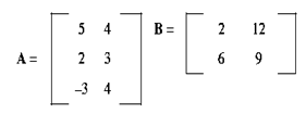
1. When two matrices are multiplied, each entry in the result is a row in the first matrix “product into” a column in the second matrix. In this product operation, each element in the first row is multiplied by a corresponding element in the second column and the results are added together.

