Inductor
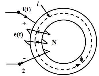
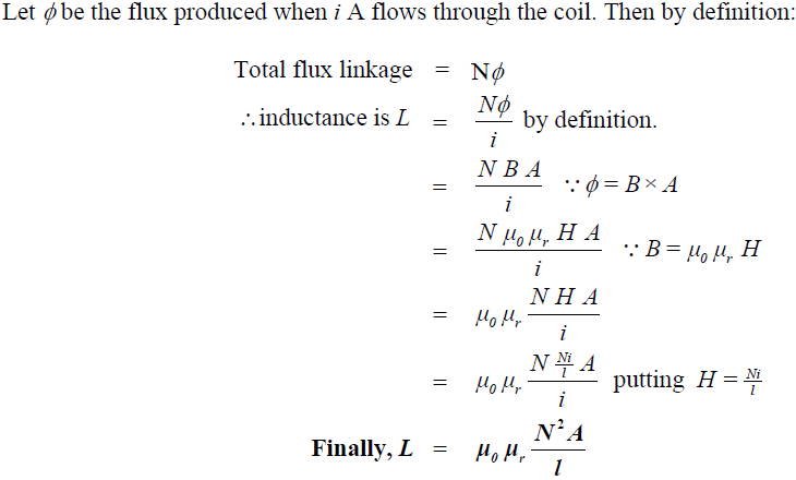
Inductor: One can make an inductor L, by having several turns N, wound over a core as shown in figure(A). In an ideal inductor, as we all know, no power loss takes place. Therefore, we must use a very good magnetic material having negligible B-H loop area. Also we must see that the operating point lies in the linear zone of the B-H characteristic in order to get a constant value of the inductance. This means μr may be assumed to be constant. To make eddy current loss vanishingly small, let us assume the lamination thickness is extremely small and the core material has a very high resistivity ρ. Under these assumptions let us derive an expression for the inductance L, in order to have a feeling on the factors it will depend upon. Let us recall that inductance of a coil is defined as the flux linkage with the coil when 1 A flows through it.
 fig(A) an inductor

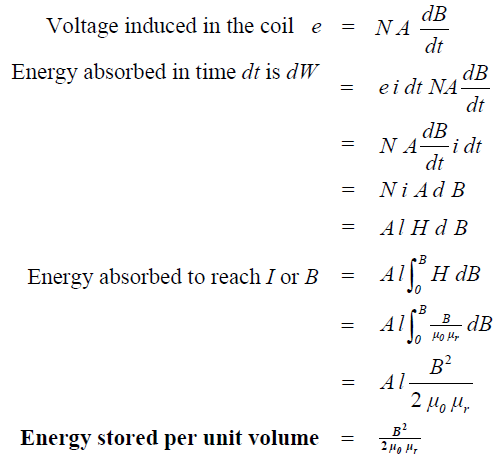
The above equation relates inductance with the dimensions of the magnetic circuit, number of turns and permeability of the core in the similar way as we relate resistance of a wire, with the dimensions of the wire and the resistivity (recall, R = lAρ). It is important to note that L is directly proportional to the square of the number of turns, directly proportional to the sectional area of the core, directly proportional to the permeability of the core and inversely proportional to the mean length of the flux path. In absence of any core loss and linearity of B-H characteristic, Energy stored during increasing current from 0 to I is exactly equal to the energy returned during decreasing current from I to 0. From our earlier studies we know for increasing current:
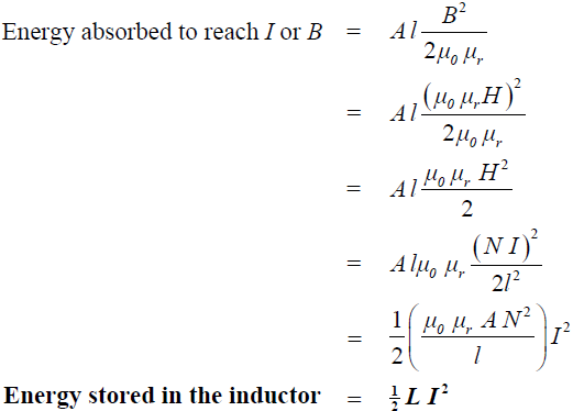
 By expressing B in terms of current, I in the above equation one can get a more familiar expression for energy stored in an inductor as follows:
