Quality Factor And Bandwidth Of A Resonant Circuit
Quality Factor and Bandwidth of a Resonant Circuit: The Q, quality factor, of a resonant circuit is a measure of the “goodness” or quality of a resonant circuit. A higher value for this figure of merit corresponds to a more narrow bandwidth, which is desirable in many applications. More formally, Q is the ration of power stored to power dissipated in the circuit reactance and resistance, respectively:
Q = Pstored/Pdissipated = I2X/I2R
Q = X/R
where: X = Capacitive or Inductive reactance at resonance
R = Series resistance.
This formula is applicable to series resonant circuits and also parallel resonant circuits if the resistance is in series with the inductor. This is the case in practical applications, as we are mostly concerned with the resistance of the inductor limiting the Q. Note: Some text may show X and R interchanged in the “Q” formula for a parallel resonant circuit. This is correct for a large value of R in parallel with C and L. Our formula is correct for a small R in series with L.
A practical application of “Q” is that voltage across L or C in a series resonant circuit is Q time’s total applied voltage. In a parallel resonant circuit, current through L or C is Q times the total applied current.
Series resonant circuits:
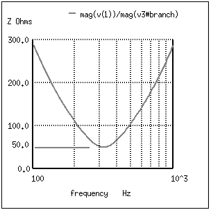
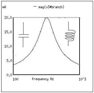
A series resonant circuit looks like a resistance at the resonant frequency. (Figure below) Since the definition of resonance is XL=XC, the reactive components cancel, leaving only the resistance to contribute to the impedance. The impedance is also at a minimum at resonance. (Figure below) Below the resonant frequency, the series resonant circuit looks capacitive since the impedance of the capacitor increases to a value greater than the decreasing inducitve reactance, leaving a net capacitive value. Above resonance, the inductive rectance increases, capacitive reactance decreases, leaving a net inductive component.
At resonance the series resonant circuit appears purely resistive. Below resonance it looks capacitive. Above resonance it appears inductive.
Current is maximum at resonance, impedance at a minumum. Current is set by the value of the resistance. Above or below resonance, impedance increases.