Series R, L, And C
Notice that I'm assuming a perfectly reactive inductor and capacitor, with impedance phase angles of exactly 90 and -90o, respectively. Although real components won't be perfect in this regard, they should be fairly close. For simplicity, I'll assume perfectly reactive inductors and capacitors from now on in my example calculations except where noted otherwise.
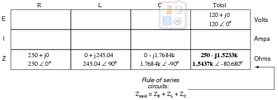
Since the above example circuit is a series circuit, we know that the total circuit impedance is equal to the sum of the individuals, so:
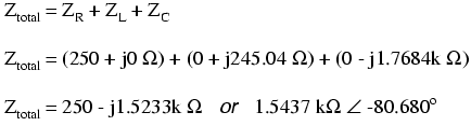
Inserting this figure for total impedance into our table:
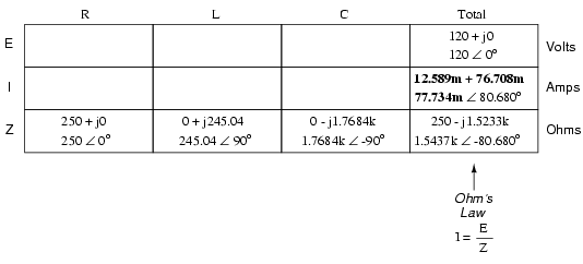
We can now apply Ohm's Law (I=E/R) vertically in the “Total” column to find total current for this series circuit:
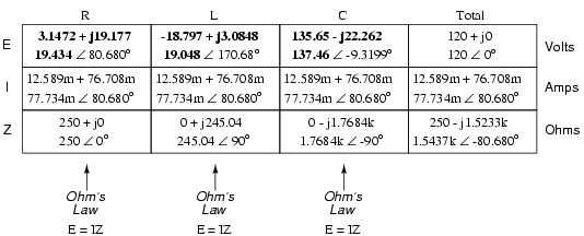
Being a series circuit, current must be equal through all components. Thus, we can take the figure obtained for total current and distribute it to each of the other columns:
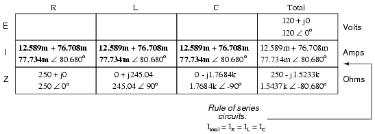
Now we're prepared to apply Ohm's Law (E=IZ) to each of the individual component columns in the table, to determine voltage drops: