Three Phase Synchronous Motor
Three Phase synchronous motor: A 3-phase synchronous motor as shown in Figure below generates an electrically rotating field in the stator. Such motors are not self starting if started from a fixed frequency power source such as 50 or 60 Hz as found in an industrial setting. Furthermore, the rotor is not a permanent magnet as shown below for the multi-horsepower (multi-kilowatt) motors used in industry, but an electromagnet. Large industrial synchronous motors are more efficient than induction motors. They are used when constant speed is required. Having a leading power factor, they can correct the AC line for a lagging power factor.
The three phases of stator excitation add vectorially to produce a single resultant magnetic field which rotates f/2n times per second, where f is the power line frequency, 50 or 60 Hz for industrial power line operated motors. The number of poles is n. For rotor speed in rpm, multiply by 60.
        S = f120/n

        where: S = rotor speed in rpm
               f = AC line frequency
               n = number of poles per phase
The 3-phase 4-pole (per phase) synchronous motor (Figure below) will rotate at 1800 rpm with 60 Hz power or 1500 rpm with 50 Hz power. If the coils are energized one at a time in the sequence φ-1, φ-2, φ-3, the rotor should point to the corresponding poles in turn. Since the sine waves actually overlap, the resultant field will rotate, not in steps, but smoothly. For example, when the φ-1 and φ-2 sinewaves coincide, the field will be at a peak pointing between these poles. The bar magnet rotor shown is only appropriate for small motors. The rotor with multiple magnet poles (below right) is used in any efficient motor driving a substantial load. These will be slip ring fed electromagnets in large industrial motors. Large industrial synchronous motors are self started by embedded squirrel cage conductors in the armature, acting like an induction motor. The electromagnetic armature is only energized after the rotor is brought up to near synchronous speed.
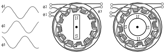
Three phase, 4-pole synchronous motor
Small multi-phase synchronous motors (Figure above) may be started by ramping the drive frequency from zero to the final running frequency. The multi-phase drive signals are generated by electronic circuits, and will be square waves in all but the most demanding applications. Such motors are known as brushless DC motors. True synchronous motors are driven by sine waveforms. Two or three phase drive may be used by supplying the appropriate number of windings in the stator. Only 3-phase is shown above.
\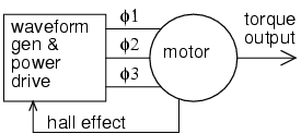
Electronic synchronous motor
The block diagram (Figure above) shows the drive electronics associated with a low voltage (12 VDC) synchronous motor. These motors have a position sensor integrated within the motor, which provides a low level signal with a frequency proportional to the speed of rotation of the motor. The position sensor could be as simple as as solid state magnetic field sensors such as Hall effect devices providing commutation (armature current direction) timing to the drive electronics The position sensor could be a high resolution angular sensor such as a resolver, an inductosyn (magnetic encoder), or an optical encoder.
If constant and accurate speed of rotation is required, (as for a disk drive) a tachometer and phase locked loop may be included. (Figure below) This tachometer signal, a pulse train proportional to motor speed, is fed back to a phase locked loop, which compares the tachometer frequency and phase to a stable reference frequency source such as a crystal oscillator.
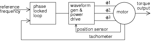
Phase locked loop controls synchronous motor speed.