←
Control Systems - 1
Lag Compensator Using Operational Amplifiers
Lag compensator using operational amplifiers

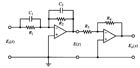
Fig: 1
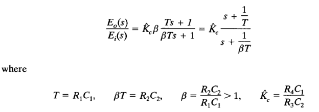
The configuration of the electronic lag compensator using operational amplifiers is the same as that for the lead compensator shown in Figure 1. If we choose R2C2 > R1C1 in the circuit shown in Figure 1, it becomes a lag compensator. Referring to Figure 1, the transfer function of the lag compensator is given by

Note that we use β instead of α in the above expressions. [In the lead compensator we used α to indicate the ratio R2C2/(R1 C1 ), which was less than 1, or 0 < α < 1.] Here we always assume that 0 < α < 1 and β > 1.