Typical Real-time Applications
Introduction: In this section we describes several representative classes of real-time applications: digital control, optimal control, command and control, signal processing, tracking, real-time databases, and multimedia.
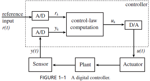
DIGITAL CONTROL: Many real-time systems are embedded in sensors and actuators and function as digital controllers. Figure 1–1 shows such a system. The term plant in the block diagram refers to a controlled system, for example, an engine, a brake, an aircraft, a patient. The state of the plant is monitored by sensors and can be changed by actuators. The real-time (computing) system estimates from the sensor readings the current state of the plant and computes a control output based on the difference between the current state and the desired state (called reference input in the figure). We call this computation the control-law computation of the controller. The output thus generated activates the actuators, which bring the plant closer to the desired state.
Sampled Data Systems: Long before digital computers became cost-effective and widely used, analog (i.e., continuoustime and continuous-state) controllers were in use, and their principles were well established. Consequently, a common approach to designing a digital controller is to start with an analog controller that has the desired behavior. The analog version is then transformed into a digital (i.e., discrete-time and discrete-state) version. The resultant controller is a sampled data system. It typically samples (i.e., reads) and digitizes the analog sensor readings periodically and carries out its control-law computation every period. The sequence of digital outputs thus produced is then converted back to an analog form needed to activate the actuators.
A Simple Example. As an example, we consider an analog single-input/single-output PID (Proportional, Integral, and Derivative) controller. This simple kind of controller is commonlyused in practice. The analog sensor reading y(t) gives the measured state of the plant at time t. Let e(t) = r (t) − y(t) denote the difference between the desired state r (t) and the measured state y(t) at time t . The output u(t) of the controller consists of three terms: a term

that is proportional to e(t), a term that is proportional to the integral of e(t) and a term that is proportional to the derivative of e(t).
In the sampled data version, the inputs to the control-law computation are the sampled values yk and rk, for k = 0, 1, 2, . . . , which analog-to-digital converters produce by sampling and digitizing y(t) and r (t) periodically every T units of time. ek = rk − yk is the kth sample value of e(t). There are many ways to discretize the derivative and integral of e(t). For example, we can approximate the derivative of e(t) for (k − 1)T ≤ t ≤ kT by (ek −ek−1)/T and use the trapezoidal rule of numerical integration to transform a continuous integral into a discrete form. The result is the following incremental expression of the kth output uk :
uk = uk−2 αek βek−1 γ ek−2 (1.1)
α, β, and γ are proportional constants; they are chosen at design time.1 During the kth sampling period, the real-time system computes the output of the controller according to this expression. You can see that this computation takes no more than 10–20 machine instructions. Different discretization methods may lead to different expressions of uk , but they all are simple to compute.
From Eq. (1.1), we can see that during any sampling period (say the kth), the control output uk depends on the current and past measured values yi for i ≤ k. The future measured values yi ’s for i > k in turn depend on uk . Such a system is called a (feedback) control loop or simply a loop. We can implement it as an infinite timed loop:
set timer to interrupt periodically with period T ;
at each timer interrupt, do
do analog-to-digital conversion to get y;
compute control output u;
output u and do digital-to-analog conversion;
end do;
Here, we assume that the system provides a timer. Once set by the program, the timer generates an interrupt every T units of time until its setting is cancelled.