D.c Machine Armature Winding
D.C machine Armature Winding: Armature winding of a D.C machine is always closed and of double layer type. Closed winding essentially means that all the coils are connected in series forming a closed circuit. The junctions of the consecutive coils are terminated on copper bars called commutator segments. Each commutator segment is insulated from the adjacent segments by mica insulation. For reasonable understanding of armature winding, let us first get acquainted with the following terminologies
• A coil has two coil sides occupying two distinct specified slots. Generally two maximize induced voltage in a coil, the spacing between them should be close to 180° electrical. This essentially means if at a given time one coil side is under the center of the north pole, the other coil side should be under the center of the south pole.
• Coil span is nothing but the spacing between the two coil sides of a coil. The spacing is expressed in terms of number of slots between the sides. If S be the total number of slots and P be the total number of poles then coil span is S/P. For 20 slots, 4 poles winding, coil span is 5. Let the slots be numbered serially as 1, 2,…, 20. If one coil side is placed in slot number 3, the other coil side of the coil must occupy slot number 8 (= 3 5).
• A Double layer winding means that each slot will house two coil sides (obviously belonging to two different coils). Physically one coil side is placed in the lower portion of the slot while the other is placed above it. It is because of this reason such an arrangement of the winding is called a double layer winding. In the n th slot, coil side in the upper deck is numbered as n and the coil side in the lower deck is numbered as n'. In the 5th slot upper coil side is numbered as 5 and the lower coil side is numbered 5'. In the winding diagram, upper coil side is shown with firm line while the lower coil side is shown with dashed line.
Remembering that a coil has two coil sides, for a double layer winding total number of coils must be equal to the total number of slots.
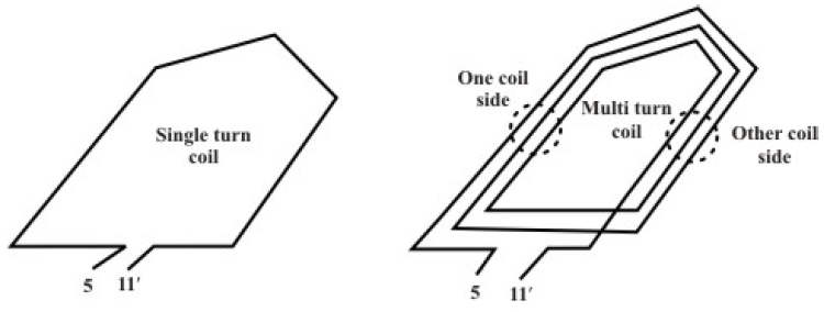
• Numbering a coil: A coil is so shaped, that when it is placed in appropriate slots, one coil side will be in the upper deck and the other side will be in the lower deck. Suppose S = 20 and P = 4, then coil span is 5. Let the upper coil side of this coil be placed in slot number 6, the other coil side must be in the lower deck of slot number 11. The coil should now be identified as (5 - 11'). In other words coil sides of a coil are numbered depending on the slot numbers in which these are placed. A typical single turn and multi turn coils are shown in figure (A)
• On a Commutator segment two coil sides (belonging to two different coils) terminate. 2S being the total number of coil sides, number of commutator segments must be equal to S, number of slots. Commutator segments can also be numbered as 1,2,…,20 in order to identify them clearly.
• Commutator pitch: As told earlier, the free ends of the coil sides of a coil (say, 6 – 11’) are to be terminated on to two specific commutator segments. The separation of coil sides of a coil in terms of number of commutator segments is called the commutator pitch, yc. In fact the value of yc decides the types of winding (lap or wave) which will result. For example, in case of lap winding yc = 1.
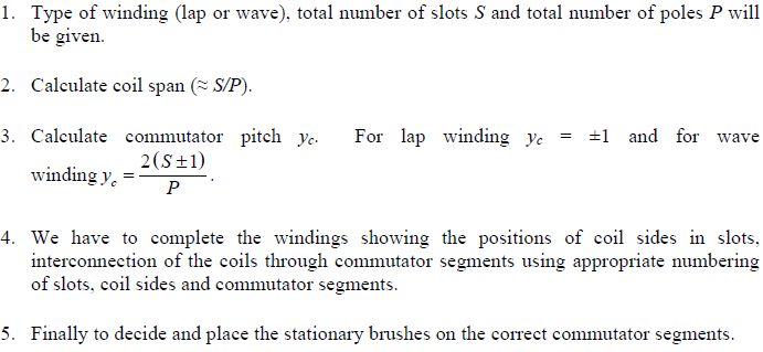
Armature winding: General procedure: